
Summary of Contents for Cermetek CH232BGN
- Page 1 CH232BGN Embedded WiFi Module User Manual Cermetek Microelectronics, Inc Page 1 of 42 Document NO. 607-00xx Revision A (12/13)
-
Page 2: Table Of Contents
UART CONFIGURATION PAGE ACCOUNT CONFIGURATION PAGE AT+ COMMAND INTRODUCTION CONFIGURATION MODE AT+ COMMANDS APPENDIX A EVALUATION BOARD REFERENCE DESIGN APPENDIX B EXTERNAL POWER SHUTDOWN MODE REFERENCE DESIGN CONTACT INFORMATION Cermetek Microelectronics, Inc Page 2 of 42 Document NO. 607-00xx Revision A (12/13) -
Page 3: Product Overview
1. PRODUCT OVERVIEW 1.1. General Specifications Table 1: CH232BGN Technical Specifications Class Item Parameters Certification FCC/CE Wireless standard 802.11 b/g/n Frequency range 2.412GHz-2.484GHz 802.11b: +20 dBm (Max.) 802.11g: +18 dBm (Max.) Transmit Power Wireless 802.11n: +15 dBm (Max.) Parameters Configurable 802.11b: -89 dBm... -
Page 4: Hardware Introduction
1.2. Hardware Introduction 1.2.1. CH232BGN Pin Definitions Figure 1: CH232BGN Pin Assignments Cermetek Microelectronics, Inc Page 4 of 42 Document NO. 607-00xx Revision A (12/13) - Page 5 Table 2: CH232BGN Pin Descriptions Description Name Direction Notes 3.5V Power 3.3V maximum 350 mA power input Ground Power Ground UART Receive Data UART_RXD Output If the UART is not used this pin can serve as a general General Purpose I/O...
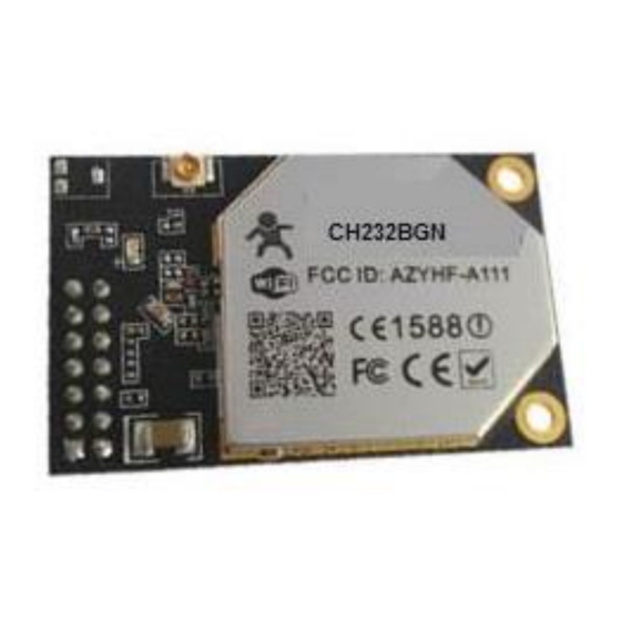
- Page 6 10MM from the antenna. Figure 3: CH232BGN Circuit Board We recommend that the CH232BGN module be placed in a corner of the user’s circuit board. This location provides optimal placement for antenna efficiency and helps to isolate the module from other circuits.
- Page 7 1.2.4. External Antenna CH232BGN modules support internal antenna and external antenna options. If user selects to use an CH232BGN external antenna, modules must be connected to the 2.4G antenna according to IEEE 802.11b/g/n standards. The antenna parameters required as follows:...
-
Page 8: Hardware Reference Design
1.3.1. Hardware Typical Application Figure 5: CH232BGN Hardware Typical Application Notes:nRST is an active low input serving as the CH232BGN hardware reset signal. The signal includes a 100K Ohm pull-up resister. This signal must be asserted for at least 300 milliseconds when power is initially applied to the module. - Page 9 Figure 6: Ethernet Reference Design with Transformer 1.3.3. UART Interface UART interface is the serial data transmission interface primarily used for the CH232BGN. The User can add RS-232 drivers on their board to convert the signals to RS-232 voltage levels for communications with outside equipment or sensors.
-
Page 10: Software Reference Design
WiFi operation the module draws about 200mA. Current draw with WiFi OFF is 100mA. Cermetek recommends decoupling be added at the power pin of the CH232BGN. At least one 100uF and one 10uF capacitor are recommended for maximum reliability and performance. The decoupling capacitors should be added as close to the CH2332BGN power pin as possible. - Page 11 AT+ commands described in Chapter 4. 1.4.3. Multi-TCP Link Connection When the CH232BGN module is configured as TCP Server, it supports Multiple TCP connections. A maximum of 32 TCP clients can connect to one CH232BGN module. Figure 9 below illustrates Multiple TCP Connections Upstream: Data from each TCP connection or client is transmitted to the serial port in sequence.
- Page 12 Notes: Pins 3, 4, 5, 6, 8, 9, 10 can be used as GPIO. Pins 4 and 10 can only be defined as inputs, while Pin 3 can only be defined as an output. The CH232BGN responds with GPIO OK if the I/O signal is active and GPIO NOK if the I/O signal is not active.
- Page 13 Notes: This nReady output function is user selected. The AT+RELD command does not operate when this function is active. If user not requires RELD, the default factory setting is Status One. Cermetek Microelectronics, Inc Page 13 of 42 Document NO. 607-00xx Revision A (12/13)
-
Page 14: Functional Description
2. FUNCTIONAL DESCRIPTION 2.1. Wireless Networking The CH232BGN module can be configured to operate as either a WiFi Station (STA) or Access Point (AP). Internally the CH232BGN incorporates separate interfaces for a WiFi Station or Access Point. When the CH232BGN works as an Access Point, other Stations are able to connect to the wireless LAN via the CH232BGN module. - Page 15 Figure 12: CH232BGN Adhoc Network Structure 2.1.3. Access Point Plus Station Wireless Network The CH232BGN module can simultaneously serve as both an Access Point and a Station. Figure 13 below illustrates this type of network., Figure 13 CH232BGN Access Point Plus Station Network...
-
Page 16: Auto-Frequency Function
CH232BGN. The CH232BGN Station Interface connects to the router and then to the TCP server in the network. At the same time the CH232BGN Access Point interface is also active. This permits a mobile phone or tablet to connect to the module through a secondary TCP connection for remote access to module parameters. -
Page 17: Uart Frame Scheme
(default 50ms), the CH232BGN interprets the interval as the end of a frame and immediately transfers this frame to the WiFi port. If there is no pause in the data, the CH232BGN buffers up to 4K Bytes of data before transferring the data as a frame to the WiFi port. -
Page 18: Wireless Distribution System (Wds)
Ethernet interface will receive an assigned IP address. Figure 15 shows, PC1 on the sub-network able to initiate a connection with PC2 (With CH232BGN serving as a router). PC2 cannot initiate a connection to PC1. -
Page 19: Search Function For Station
Access Points. 2.9. Work Mode CH232BGN modules communicate only in “Transparent Transmission Mode.” Transparent transmission mode provides a plug and play serial data port reducing system complexity. On power up the module will attempt to connect with a compatible wireless network. The parameters which need to be configured include: ... -
Page 20: Parameters Configuration
Work Mode Selection (AT+TMODE) Transparent transmission Transparent transmission mode is illustrated in Figure 18. The CH232BGN modules serve as a wireless serial link. Data is sent between user devices without modification. Figure 18: CH232BGN Transparent Transmission Operation 2.10. Parameters Configuration CH232BGN module supports two methods of configuring parameters;... -
Page 21: Online Configuration
The CH232BGN module may require configuration to establish a wireless connection. The default wireless configuration of the CH232BGN is shown in table 5 below. This information can be modified by entering AT+ commands to the CH232BGN through the serial port. -
Page 22: Access Point Interface Configuration Page
Access Point Interface Configuration Page Figure 20, below, allows the user to set the parameters to be used when the CH232BGN module works as an Access Point. Options include the WiFi networking mode (802.11 b, g, or n), network ID, Security Mode, and LAN setup. -
Page 23: Uart Configuration Page
No IP Address is required when the CH322BGN is used as a TCP server. The Port ID must be the same for the devices on each end of the communications link. Cermetek Microelectronics, Inc Page 23 of 42 Document NO. 607-00xx Revision A (12/13) - Page 24 Account Administrator Configuration This page manages the administrative settings of the CH232BGN module. These settings include the account identification, module re-start, reload factory defaults and on-line firmware upgrade. Figure 23: Administrative Configuration Page Notes: When parameters are set on-line, the “Apply” button on the bottom of the page confirms the new settings;...
-
Page 25: Configuration Mode
Figure 3 CH232BGN Default UART Port Parameters There are two steps to switch from transparent transmission mode to configuration mode. Step 1: Send the text string “+++” to the CH232BGN. The module responds with “a” to confirm receipt of the command. - Page 26 - Carriage Return, ASCII 0x0d; <LF>: - Line Feed, ASCIII 0x0a; 4.2.4 Error Codes Table 6 below list the Error codes for the CH232BGN AT+ commands Table 6: Error Code Description (CH232BGN Web Access Default Settings) Error Code Description Invalid Command Format...
- Page 27 Re-start module Query module ID information Query module software version information Help Notes: CH232BGN module can operate as an Access Point or Station. Access Points and Stations require different AT+ command settings. Cermetek Microelectronics, Inc Page 27 of 42 Document NO. 607-00xx Revision A (12/13)
- Page 28 CS = SERVER or CLENT Port = Protocol ID Number 0 to 65535 IP = Server IP Address (Only when the CH232BGN is configured as a Client) Note: New settings for AT+NETP do not become active until the CH232BGN module reboots.
- Page 29 = NONE, EVEN, ODD, MARK, SPACE flowctrl (hardware flow control) = NFC (no flow control) or FC (Flow Control Active) Note: New settings for the AT+UART command do not become active until the CH232BGN module reboots. 4.2.5.5 AT+UARTF: This command allows the user to read or control the auto-frame function of the serial port.
- Page 30 = through; Transparent transmission selected; = Agreement; Agreement transmission selected Note: New settings for AT+TMODE do not become active until the CH232BGN module reboots. 4.2.5.9 AT+WMODE: This command allows the user to read or set the WiFi Mode. Read WiFi Mode AT+WMODE<CR>...
- Page 31 Parameters: ap’s ssid = Service Set identifier of the local Access Point Note: New settings for AT+WSSID do not become active until the CH232BGN module reboots. This command is only active in Station mode. Cermetek Microelectronics, Inc Page 31 of 42...
- Page 32 = “RF Off (WiFi disabled) Note: New settings for AT+WSLK do not become active until the CH232BGN module reboots. This command is only active in Station mode. 4.2.5.13 AT+WEBU: This command allows the user to Set or Read Web Page login parameters Read Web Page Login Parameters AT+WEBU<CR>...
- Page 33 (password) = ASCII code between 8 and 64 bits; Note: New settings for AT+WAKEY do not become active until the CH232BGN module reboots. This command is only active in Station mode. 4.2.5.16 AT+MSLP: This command Sets the module into power saving mode and allows the user to read which mode is active.
- Page 34 =Searched for Access Point Note: This command is only active in Station mode. 4.2.5.18 AT+ TCPLK: This command checks the CH232BGN to see if a TCP link is established. Confirm presence of a TCP Link AT+TCPLK<CR> +ok=<sta><CR>< LF ><CR>< LF >...
- Page 35 = WAN port gateway address Note: New settings for AT+WANN do not become active until the CH232BGN module reboots. This command functions only in Station mode. 4.2.5.21 AT+ LANN: This command Sets and Reads the Local Area network (LAN) parameters.
- Page 36 Parameters: num (Maximum Number of Connections) = 1-32 Note: When configured as a TCP/Server, the CH232BGN can support a maximum of 32 TCP connections. The user can reset this parameter if fewer connections are required. Cermetek Microelectronics, Inc Page 36 of 42...
- Page 37 = on (TCPB Enabled) = off (TCPB Disabled Note: New settings for AT+TCPB do not become active until the CH232BGN module reboots. 4.2.5.26 AT+TCPPTB: This command permits the user to Set or Read the TCPB port number. Read TCPB Port Number AT+TCPPTB<CR>...
- Page 38 = 0 (no timeout) Default value is 300 seconds Note: New settings for AT+TCPTOB do not become active until the CH232BGN module reboots. 4.2.5.29 AT+TCPLKB: This command allows the user to Read TCPB link status. Read TCPB Link Status AT+TCPCKB<CR>...
- Page 39 4.2.5.32 AT+RELD: This command restores the module to factory default setting, and then re-starts the module. Restore Factory Defaults AT+RELD<CR> +ok=rebooting…<CR>< LF ><CR>< LF > 4.2.5.33 AT+Z: This command restarts the CH232BGN. Restart Module: AT+Z<CR> 4.2.5.34 AT+MID: Request Module ID; Request Module ID AT+MID<CR>...
-
Page 40: Appendix Aevaluation Board Reference Design
APPENDIX A: EVALUATION BOARD REFERENCE DESIGN Cermetek Microelectronics, Inc Page 40 of 42 Document NO. 607-00xx Revision A (12/13) -
Page 41: Appendix Bexternal Power Shutdown Mode Reference Design
APPENDIX B: EXTERNAL POWER SHUTDOWN MODE REFERENCE DESIGN Cermetek Microelectronics, Inc Page 41 of 42 Document NO. 607-00xx Revision A (12/13) -
Page 42: Contact Information
CONTACT INFORMATION ---------------------------------------------------------------------------------------------------------------- Cermetek Microelectronics, Inc. 374 Turquoise Street, Milpitas, CA 95035 www.cermetek.com Tel: 408-942-2200 Fax: 408-942-1346 Email: sales@cermetek.com Cermetek Microelectronics, Inc Page 42 of 42 Document NO. 607-00xx Revision A (12/13)