Table of Contents
Advertisement
Warning:
This water heater is not
!
suitable for use in manufactured (mobile) homes!
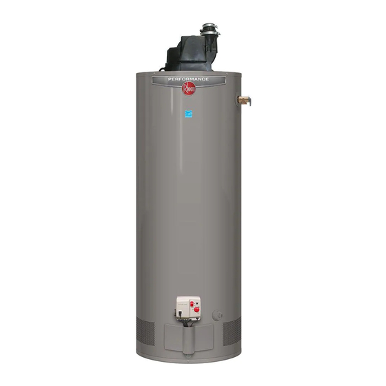
Residential Gas -
Model shown with factory installed
optional digital display.
WARNING: If the information in these instructions is not followed exactly, a fire or
!
explosion may result causing property damage, personal injury or death.
FOR YOUR SAFETY!
!
— Do not store or use gasoline or other
flammable vapours or liquids or other
combustible materials in the vicinity of this or
any other appliance. To do so may result in an
explosion or fire.
— WHAT TO DO IF YOU SMELL GAS
Do not try to light any appliance.
●
Do not touch any electrical switch; do not
●
use any phone in your building.
Immediately call your gas supplier from
●
a neighbour's phone. Follow the gas
supplier's instructions.
Printed in USA
Use & Care Manual
With Installation Instructions for the Installer
FVIR Certified
The purpose of this manual is twofold: one, to provide the installer with the basic
directions and recommendations for the proper installation and adjustment of the
water heater; and two, for the owner–operator, to explain the features, operation,
safety precautions, maintenance and troubleshooting of the water heater. This
manual also includes a parts list.
It is very important that all persons who are expected to install, operate or adjust this
water heater read the instructions carefully so they may understand how to perform
these operations. If you do not understand these instructions or any terms within it,
seek professional assistance.
Any questions regarding the operation, maintenance, service or warranty of this
water heater should be directed to the seller from whom it was purchased. If
additional information is required, refer to the section on "If you need service."
Do not destroy this manual. Please read carefully and keep in a safe place for
future reference.
!
Recognize this symbol as an indication of Important Safety Information!
Water Heaters
®
Residential 40 and 50 Gallon
If you cannot reach your gas supplier, call the
●
fire department.
Do not return to your home until authorized
●
by the gas supplier or fire department.
— Improper installation, adjustment, alteration,
service or maintenance can cause property
damage, personal injury, or death. Refer to
this manual. Installation and service must be
performed by a qualified installer, service
agency or the gas supplier.
AP15763-2 (01/14)
Advertisement
Table of Contents

Related Manuals for Rheem PowerVent Series


Summary of Contents for Rheem PowerVent Series
- Page 1 Use & Care Manual Warning: This water heater is not suitable for use in manufactured (mobile) homes! With Installation Instructions for the Installer Residential Gas - FVIR Certified Water Heaters ® Residential 40 and 50 Gallon The purpose of this manual is twofold: one, to provide the installer with the basic directions and recommendations for the proper installation and adjustment of the water heater;...
-
Page 2: Table Of Contents
Safety Information FOR YOUR RECORDS Safety Precautions ..3–6 LP Gas Models ... 5 Write the model and serial numbers here: Installation Instructions You can find them on a label on the appliance. Location . - Page 3 IMPORTANT SAFETY INFORMATION. READ ALL INSTRUCTIONS BEFORE USING. Be sure to read and understand the entire Use and Care Manual before attempting to install or operate this water heater. It may save you time and money. Pay particular attention to the Safety Instructions. Failure to follow these warnings could result in serious bodily injury or death.
- Page 4 IMPORTANT SAFETY INFORMATION. READ ALL INSTRUCTIONS BEFORE USING. DANGER! WATER TEMPERATURE SETTING Safety and energy conservation are factors to be considered when selecting the water temperature setting of a water heater’s gas control. Water temperatures above 125°F (52° C) can cause severe burns or death from scalding. Be sure to read and follow the warnings outlined on the label pictured below.
- Page 5 DANGER! LIQUEFIED PETROLEUM (LP - PROPANE - BUTANE) AND NATURAL GAS MODELS LP and Natural gas have an odorant added to aid in detecting a gas leak. Some people may not physically be able to smell or recognize this odorant. If you are unsure or unfamiliar with the smell of LP or natural gas, ask the gas supplier.
-
Page 6: Safety Precautions
IMPORTANT SAFETY INFORMATION. READ ALL INSTRUCTIONS BEFORE USING. WARNING! For your safety, the information in this manual must be followed to minimize the risk of fire or explosion, electric shock, or to prevent property damage, personal injury, or loss of life. -
Page 7: Location
Installing the water heater This water heater must be installed in accordance with these instructions, local codes, utility company requirements, and/or in the absence of local codes, use the latest edition of CAN/CSA B149 - Natural Gas and Propane Installation Code. A copy can be purchased from the Canadian Standards Association, 5060 Spectrum Way, Mississauga, Ontario L4W 5N6. - Page 8 Installing the water heater Inspect Shipment Inspect the water heater for possible damage. Check the markings on the rating plate of the water heater to be certain the type of gas supplied corresponds to the water heater requirements. Combustion and Ventilation Air Proper operation of the water heater inches (650 sq.
-
Page 9: Water Supply Connections
Thermal Expansion Determine if a check valve exists in the inlet pressure increase in the water heater and water line. Check with your local water system piping. This rapid pressure increase can utility company. It may have been installed quickly reach the safety setting of the relief in the cold water line as a separate back flow valve, causing it to operate during each heating preventer, or it may be part of a pressure... - Page 10 Installing the water heater A new combination temperature and pressure relief valve, complying with the Standard for Relief Valves and Automatic Gas Shut-Off Devices for Hot Water Supply Systems, ANSI Z21.22, is supplied and must remain in the opening provided and marked for the purpose on the water heater. No valve of any type should be installed between the relief valve and the tank.
-
Page 11: Gas Supply
WARNING: DO NOT attempt to convert this water heater for use with a different type of gas other than the type shown on the rating plate. Such conversion could result in hazardous operating conditions. Gas Supply The branch gas supply line to the water as part of the appliance, a sediment trap heater should be clean 1/2”... -
Page 12: Venting
Installing the water heater The water heater must be installed with the factory supplied blower assembly in place. Blower Assembly Installation Blower Assembly NOTICE: The Blower Assembly is Connect blower assembly with the model specific and only the blower electrical connector. Attach Blower Rubber assembly supplied should be used on Assembly to top pan using the six (6) - Page 13 Vent Pipe Materials NOTICE: This unit can be vented using only Note: It is acceptable to interchange PVC the following recommended pipe material. and CPVC pipe and fittings. 2 inch: PVC (Schedule 40, ASTM D1785) NOTE: This water heater may be installed in attics provided ambient temperatures 3 inch: PVC (Schedule 40, ASTM D1785) DO NOT exceed 125°F (52°C) and CPVC...
- Page 14 Installing the water heater Condensate Management and Vent Risers There is no condensate collection and disposal Water required for Rheem water heaters under most Filled conditions. Installations where the vent run is From Drain Port short or it runs through conditioned space in the...
- Page 15 Maximum and Minimum Vent Lengths for Residential 40 & 50 Gallon Power Vents ONLY Minimum vent length for 2”vent pipe is one (1) foot (30.4 cm)of vertical pipe, one (1) 90°elbow, and three (3) feet (0.91 m) of horizontal pipe. Maximum Venting information for 2”...
- Page 16 Installing the water heater Additional Venting Requirements Installations requiring less than one (1) foot of vertical pipe before the first elbow, subtract six (6) feet from the maximum vent length. Less than 1 ft. vertical pipe before first elbow Minimum Vent Restrictor Install the vent restrictor only at the minimum vent lengths listed on page 15.
- Page 17 Vent Terminal Clearances V = Vent Terminal X = Air Supply Inlet Αrea Where Terminal Is Not Permitted Canada Installations² Clearance above grade, veranda, porch, 12 in. (30 cm) deck or balcony 6 in. (15 cm) for appliances ≤ 10,000 Btuh (3 kW), 12 in (30 cm) for Clearance to window or door that may be 10,000 Btuh (3 kW) and ≤...
- Page 18 Installing the water heater Additional Considerations DO NOT install vent terminal under any patio or deck. Caulk Rising moisture will To help prevent moisture from freezing on walls and under collect under eaves eaves, do not locate vent terminal on the side of a build ing If soffit vent is too with prevailing winter winds.
- Page 19 NOTICE: Follow the CAN/CSA B149.1 and vent system manufacturer's installation instructions for proper installation of the vent system. Horizontal Vent Installation 2' x 2' (60 cm x 60cm) Sheet Metal Shield Once the vent terminal location has been determined, make a on Brick or Masonry hole through the exterior wall to accommodate the vent pipe.
-
Page 20: Wiring Diagram
Installing the water heater Wiring If local codes permit, the water heater may The maximum current draw is be connected to electric service with the approximately 5.0 amps. power cord provided (DO NOT use an The water heater must be electrically extension cord). - Page 21 Diagram With Optional Electronic Display CAUTION! Label all wires prior to disconnection when servicing controls. Wiring errors can cause improper and dangerous operation. VERIFY PROPER OPERATION AFTER SERVICING!
-
Page 22: Pipe Insulation
Installing the water heater Insulation Blankets Insulation blankets, available to the CAUTION: If local codes require the general public, for external use on gas WARNING: If local application of an external insulation water heaters are not necessary. The codes require external blanket to this water heater, pay careful purpose of an insulation blanket is to application of insulation... -
Page 23: Install User Display
Installing the User Display The following instructions apply only to water heater models factory supplied with the electronic display option. IMPORTANT NOTICE: This electronic display cannot Mounting Holes be added to a water heater not supplied from the for Transformer factory with an electronic display. - Page 24 12. Remove tape backing and carefully attach to the heater 18. Remote mounting will not require the Display to jacket above the Rheem logo. Allow the thermostat Heater Bracket or Display Mounting Tape. The bracket wire to be positioned in the wire slot located on the may be kept for future use or recycled.
- Page 25 Water Heater Optional User Display - Operation Instructions Display Temperature Setting Limits After power on, all segments on the LCD will be User Mode is entered after all required data is received displayed for 2 seconds, (See Diagram A) followed by from the appliance when powered-up.
-
Page 26: User Display Operation
Water Heater Optional User Display - Operation Instructions Display Temperature Setting Limits The user display setpoint temperature cannot The water heater gas valve knob below is set to exceed maximum water heater valve setpoint HOT therefore the user display shows Hot as the temperature at any time. - Page 27 Installing the water heater continued..Estimated Hot Water Three bars shown on the user display are an estimate of hot water available relative to the temperature setpoint. The chart below describes what each symbol means. Est. Hot Water Tank is full of hot water Est.
-
Page 28: Heat Traps
Installing the water heater Heat Traps For increased energy efficiency, some These heat traps may require a minimum water heaters have been supplied with of one (1) 90° 3/4” NPT elbow and may factory installed 3/4” NPT heat traps in the require an additional 90°... -
Page 29: Installation Checklist
Installation Checklist A. Water Heater Location ❑ Close to area of vent. ❑ Provisions made to protect area from water damage. ❑ Indoors and protected from freezing temperatures. ❑ Sufficient room to service heater. Proper clearance from combustible surfaces Combustible materials, such as clothing, ❑... -
Page 30: Potable/Space Heating
Supplemental instructions for gas water heaters installed in potable water/space heating applications. Local codes or plumbing authority requirements may vary from the instructions or diagrams provided in this manual and take precedent over these instructions. Combination Potable Water and Space Heating Application Hot water NOTICE: Suitable for combination Tee fitting must be installed as shown. -
Page 31: Operating Instructions
Lighting the water heater Before operating this water heater, be sure to read and follow the instructions on the label pictured below and all other labels on the water heater, as well as the warnings printed in this manual. Failure to do so can result in unsafe operation of the water heater resulting in property damage, personal injury, or death. - Page 32 Operating the water heater CAUTION: Hydrogen gas can be produced in a hot water system served by this water heater that has not been used for a long period of time (generally two weeks or more). HYDROGEN GAS IS EXTREMELY FLAMMABLE!! To dissipate such gas and to reduce risk of injury, it is recommended that the hot water faucet be opened for several minutes at the kitchen sink before using any electrical appliance connected to the hot water system.
-
Page 33: Water Temperature
Operating the water heater Water Temperature Setting... The following is additional information which The gas control (thermostat) is constructed with aid in determining a safe working temperature to a built in safety shut-off device designed to meet each household need. shut off the gas supply to the burner if the main Maximum water temperatures occur just after burner is extinguished for any reason. - Page 34 Operating the water heater Sequence of Operation… 1. During initial start-up or a call for heat, the This water heater is equipped with a flammable vapor sensor that is monitored continuously by the control will verify the vacuum switch is open. electronic control in all modes of operation.
-
Page 35: Care And Cleaning
Care and cleaning of the water heater Draining the Water Heater Before turning off the cold water supply to CAUTION: Shut off gas to the water the water heater, open a hot water faucet heater at the gas control (thermostat) allowing sufficient cold water into the gas cock or manual shut-off valve before tank to prevent the risk of a scald injury... -
Page 36: Vent System Inspection
Care and cleaning of the water heater Housekeeping DANGER: Combustible Visually inspect hot surface ignitor. DO NOT obstruct or block the Flammable Vapour Sensor. The sensor does not materials, such as clothing, To ensure sufficient ventilation and require any maintenance or cleaning. cleaning materials, or combustion air supply, proper clearances flammable liquids, etc.,... -
Page 37: Extended Shut-Down
Vacation and Extended Shut-Down If the water heater is to remain idle for an After a long shut-down period, the water extended period of time, the power and heater’s operation and controls should be NOTICE: Refer to the water to the appliance should be turned off checked by qualified service personnel. -
Page 38: Troubleshooting Tips
Before You Call For Service… Troubleshooting Tips Save time and money! Review the charts on the following pages first and you may not need to call for service. This water heater incorporates a combustion shut off device that shuts the operation of the water heater down if undesirable combustion conditions occur, such as the presence of flammable vapours or blockage of the combustion air inlet openings. - Page 39 Before You Call For Service… Troubleshooting Tips Save time and money! Review the charts on the following pages first and you may not need to call for service. This water heater incorporates a combustion shut off device that shuts the operation of the water heater down if undesirable combustion conditions occur, such as the presence of flammable vapours or blockage of the combustion air inlet openings.
- Page 40 Gas Valve LED Codes LCD CODE GAS VALVE STATUS/PROBLEM PROBABLE CAUSE SOLUTION For Optional Display Short flash once IDLE (no call for heat, Temperature setpoint achieved and None No solution required every four seconds no fault conditions) burner is off “Heartbeat”, alter- Call For Heat (no fault Water temperature is below set-...
-
Page 41: Parts List
Replacement Parts For 40 and 50 gallon models using natural or LP gas. Instructions For Placing a Parts Order All parts orders should include: CAUTION: For your safety, DO NOT attempt repair of gas piping,gas control The model and serial number of the water (thermostat), burners, vent connectors or heater from the rating plate. - Page 42 Notes:...
- Page 43 Notes:...
-
Page 44: Customer Service
2. Should your problem not be solved to your complete satisfaction, you should then contact the Manufacturer’s National Service Department at the following address: Rheem Canada Ltd./Ltee 125 Edgeware Road, Unit 1 Brampton, Ontario Canada L8Y 0P5 Customer Service Phone: 1-800-432-8373.
Need help?
Do you have a question about the PowerVent Series and is the answer not in the manual?
Questions and answers