Table of Contents
Advertisement
User Manual
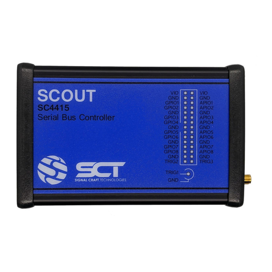
SC4415 - Scout
Number: SCT-UM026Fvc
Date: 2019-08-23
This document contains proprietary information and shall not be disclosed, in whole or in part, to any party
without the expressed and written consent of an authorized representative of SignalCraft Technologies Inc. ©2013
6815 – 8 Street NE, Suite 295
Calgary, AB T2E7H7 Canada
www.signalcraft.com
Advertisement
Table of Contents

Summary of Contents for SCT Scout SC4415
- Page 1 User Manual SC4415 - Scout Number: SCT-UM026Fvc Date: 2019-08-23 6815 – 8 Street NE, Suite 295 Calgary, AB T2E7H7 Canada www.signalcraft.com This document contains proprietary information and shall not be disclosed, in whole or in part, to any party without the expressed and written consent of an authorized representative of SignalCraft Technologies Inc. ©2013...
-
Page 2: Revision History
Revision History Revision Date Author Description 2017-11-03 K. Sumlak Initial Release 2019-02-20 K. Sumlak Update for release version 1980 2019-08-23 K. Sumlak Update for release version 2030 Document# SCT-UM026FVC Page 2 of 46 Confidential... -
Page 3: Table Of Contents
Data Queue ..............................16 3.2.6 Events ................................17 Application Modes ............................18 3.3.1 Boot Mode ..............................18 3.3.2 MIPI-RFFE Mode ............................19 3.3.2.1 Summary .............................. 19 3.3.2.2 Details ..............................19 3.3.3 SPI Mode ............................... 20 Document# SCT-UM026FVC Page 3 of 46 Confidential... - Page 4 ................................31 5.2.2 hsdr ................................31 5.2.3 rr ................................... 31 5.2.4 err ................................. 32 5.2.5 erl .................................. 32 5.2.6 rzw ................................32 5.2.7 rw .................................. 32 5.2.8 erw ................................33 5.2.9 ewl ................................33 Document# SCT-UM026FVC Page 4 of 46 Confidential...
- Page 5 42 5.4.15 legacy_write ............................. 42 5.4.16 legacy_read .............................. 42 5.4.17 sdr_write ..............................43 5.4.18 sdr_read ..............................43 5.4.19 sdr_rsvd ..............................44 5.4.20 ddr_write ..............................44 5.4.21 ddr_read ..............................44 Additional Information............................46 Document# SCT-UM026FVC Page 5 of 46 Confidential...
- Page 6 Support ................................46 Regulatory ................................. 46 6.2.1 FCC Compliance ............................46 Document# SCT-UM026FVC Page 6 of 46 Confidential...
-
Page 7: Overview
Section 3 describes the unique feature set of the SC4415 such as configurable IO voltage levels, bus clock rates, operation sequence control, and protocol specific functionality. 1.2 Symbols Below are the document symbols which appear in this manual. Important Note Programming Example Document# SCT-UM026FVC Page 7 of 46 Confidential... -
Page 8: Hardware
Detail about each interface can be found by referencing the item number, shown in red, against Table 2.1-1. Item Description Section External 5VDC Input (optional) Status LED USB Device Port Ethernet Connector SMA Trigger Connector IO Interface Connector Table 2.1-1 – Device Interface Details Document# SCT-UM026FVC Page 8 of 46 Confidential... -
Page 9: Power
As a result of extracting the archive, two files can now be observed sct_scout.cat and sct_scout.inf. To install the driver, right click the sct_scout.inf file and select install as shown in Figure 2.3.1-1. Document# SCT-UM026FVC Page 9 of 46 Confidential... -
Page 10: Ethernet
Using the information in Table 2.5-1, the mechanical details of the IO Interface connector can be determined which will assist in choosing a mating connector for a custom application. Additional connector accessories are available from SignalCraft Technologies for the SC4415. Document# SCT-UM026FVC Page 10 of 46 Confidential... -
Page 11: Pin Map
Hardware Trigger. Used for triggering and TRIG synchronization. Signal ground reference. Table 2.5.1-1 – IO Pin Descriptions Figure 2.5.1-1 – IO Interface Pin Map Document# SCT-UM026FVC Page 11 of 46 Confidential... -
Page 12: Io Details
VIO to 1.2V, 1.8V, 2.5V or 3.3V. Alternatively, VIO can be configured as an input to accept an externally provided voltage which may be generated from other equipment. Table 2.5.3-1 provides the electrical specifications for VIO. Description Value Input Operating range 0.8V – 3.5V Output set-points 1.2V, 1.8V, 2.5V, 3.3V Document# SCT-UM026FVC Page 12 of 46 Confidential... -
Page 13: Status Led
Temperature Storage Temperature -40°C to 85°C Humidity 5% to 85% non-condensing HBM JESD22-A114E Class 3B exceeds 8000V ESD Protection MM JESD22-A115-A exceeds 200V CDM JESD22-C101C exceeds 1000V Table 2.7-1 – Additional Product Specifications Document# SCT-UM026FVC Page 13 of 46 Confidential... -
Page 14: Programming
The Command CMD1 does not require any arguments The Command CMD2 has two mandatory numeric arguments, ARG1 CMD2 <ARG1> <ARG2> ARG2 The Command CMD3 has one mandatory numeric argument, ARG1, CMD3 <ARG1> [<ARG2>] and one optional numerical argument, ARG2. Document# SCT-UM026FVC Page 14 of 46 Confidential... -
Page 15: Help System
Doing so enables commands to be sequenced and executed in a deterministic fashion. The Inter-command delay can be tightly controlled by inserting Delay commands. The additional delay, specified in terms of clock cycles, helps to ensure the required command timing can be achieved. Document# SCT-UM026FVC Page 15 of 46 Confidential... -
Page 16: Data Queue
The remaining data bytes can be returned with subsequent reads. # Enable Buffer Mode (Primary). ->buffer 1 # Queue two SPI Read operations. B>s_read 5 0x1 0x30 B>s_read 5 0x1 0x40 # Execute a Single Software Trigger to Document# SCT-UM026FVC Page 16 of 46 Confidential... -
Page 17: Events
In most cases, event messages can be disabled from being reported to the Programming Interface. Refer to Section 3.3 for additional detail and about mode specific event and how to configure them. Document# SCT-UM026FVC Page 17 of 46 Confidential... -
Page 18: Application Modes
The example below shows the user querying the mode of operation after Scout has been booted. The current operating mode is listed as 0 which indicates the current mode as BOOT. The next operation shows the selection of the desired operating Mode, in this case, it is SPI mode. Document# SCT-UM026FVC Page 18 of 46 Confidential... -
Page 19: Mipi-Rffe Mode
Perform an RFFE Register Write operation 5.2.7 Perform an RFFE Extended Register Write operation 5.2.8 Perform an RFFE Extended Register Write Long operation 5.2.9 Perform an RFFE Masked Register Write operation 5.2.10 Table 3.3.2.2-1 – RFFE Command List Document# SCT-UM026FVC Page 19 of 46 Confidential... -
Page 20: Spi Mode
5.3.9 wait_read Set the number of wait cycles before the read data 5.3.10 s_write Perform an SPI Write operation 5.3.11 s_read Perform an SPI Read operation 5.3.12 Table 3.3.3.2-1 – SPI Command List Document# SCT-UM026FVC Page 20 of 46 Confidential... - Page 21 The Delay Cycles can be adjusted using the Wait_read command. Once the SPI interface has been properly configured for the Slave device(s) attached, SPI Read and Write operations can be executed using the s_Read s_Write commands respectively. Document# SCT-UM026FVC Page 21 of 46 Confidential...
-
Page 22: Mipi-I3C Mode
5.4.11 vendor_write Perform a Vendor Specific CCC write operation 5.4.12 vendor_read Perform a Vendor Specific CCC read operation 5.4.13 ibi_read Request available In-Band-Interrupt data 5.4.14 legacy_write Perform a Legacy I2C write operation 5.4.15 Document# SCT-UM026FVC Page 22 of 46 Confidential... - Page 23 If a slave device sends an In-Band-Interrupt (IBI), Scout will process the request and store the data received in a temporary memory space. The IBI data will be stored in temporary memory either until the user processes the IBI data Document# SCT-UM026FVC Page 23 of 46...
- Page 24 I3C Bus Error messages have no impact on timing. However, in some cases, it may be preferable to disable the reporting of Bus Errors. Bus Error messages can be disabled using the ERR_msg command. Document# SCT-UM026FVC Page 24 of 46 Confidential...
-
Page 25: Maintenance
Once the license file has been transferred and validated, a confirmation message as shown below can be observed. License updated successfully... Execute 'license' to view activated features. Once the license update has been completed, the newly enabled features can be observed by issuing the License command. Document# SCT-UM026FVC Page 25 of 46 Confidential... -
Page 26: System Firmware
SC4415 support and to receive firmware updates. The System Firmware file, provided by SignalCraft, has a file extension of “.tar.gz” and a filename of “SCT-IM226Fvc- 1234” where 1234 is an example of the version number. It is important to take note of the version number of the new System Firmware file. -
Page 27: Reference
The available VIO settings may vary depending on the application Mode selected. Setting RFFE 0 = External VIO Reference Detail 1 = Internal 1.2 Volts 2 = Internal 1.8 Volts 3 = Internal 2.5 Volts 4 = Internal 3.3 Volts Document# SCT-UM026FVC Page 27 of 46 Confidential... -
Page 28: Led
Data bytes are presented individually in a simplified table along with the calculated odd parity for each byte. Any command which performs any type of 'read' operation will store its returned data into the Data Queue. 5.1.9 buffer Name buffer Queue Document# SCT-UM026FVC Page 28 of 46 Confidential... -
Page 29: Trigger_In
Execution of this command disables the automatic triggering and executes a manual trigger. To restore the trigger output back to the automatic mode, issue the ‘clear’ command. 5.1.12 clear Name clear Queue Synopsis clear Document# SCT-UM026FVC Page 29 of 46 Confidential... -
Page 30: Delay
(0) will ignore the Pin State. The pins of interest can be specified by setting or clearing the Pin Mask bits. For both the Pin Mask and the Pin Document# SCT-UM026FVC Page 30 of 46 Confidential... -
Page 31: Gpr
1 = Enable (half speed) 5.2.3 Name Queue Synopsis rr <SA> <ADDR> Description Perform an RFFE Register Read operation Register Read: <SA> Slave Address: Detail Address of the RFFE Slave device to communicate with. Range = 0-15 Document# SCT-UM026FVC Page 31 of 46 Confidential... -
Page 32: Err
<SA> Slave Address: Address of the RFFE Slave device to communicate with. Detail Range = 0-15 <DATA> Write Data: Data to write to register 0 (7-bit data). Range = 0x00 – 0x7F 5.2.7 Name Queue Document# SCT-UM026FVC Page 32 of 46 Confidential... -
Page 33: Erw
Low Address byte of the register to read Range = 0x00-0xFF <DATAn> Write Data: Data to write to the register specified. The number of data bytes must match the Byte Count specified. Range = 0x00 – 0xFF Document# SCT-UM026FVC Page 33 of 46 Confidential... -
Page 34: Mrw
Command Width: See 'w_command' <ADDR_WIDTH> Address Width: See 'w_address' <WR_WIDTH> Write Width: See 'w_write' <RD_WIDTH> Read Width: See 'w_read' <WAIT_CYCLES> RD Wait Cycle: See 'wait_read’ 5.3.3 select Name select Queue Synopsis select <SELECT> Document# SCT-UM026FVC Page 34 of 46 Confidential... -
Page 35: Polarity
Set the Address Word width <WIDTH> Address Word Width: Set the width of the Address Word for read and write operations. 0 = No Address Word Detail 1 = 1-Bit … 16 = 16-Bits Document# SCT-UM026FVC Page 35 of 46 Confidential... -
Page 36: W_Write
Command as specified by the SPI device manufacture. Range = 0x00 to the value of ‘w_command’ <ADDR> Register Address: Register Address as specified by the SPI device manufacture. Range = 0x00 to the value of ‘w_address’ <DATAn> Data Word(s): Document# SCT-UM026FVC Page 36 of 46 Confidential... -
Page 37: S_Read
3 = 1.000 MHz 4 = 0.400 MHz 5 = 0.200 MHz 6 = 0.100 MHz <I2C_RATE> I2C Device Clock: 0 = 1.000 MHz 1 = 0.400 MHz 2 = 0.200 MHz 3 = 0.100 MHz Document# SCT-UM026FVC Page 37 of 46 Confidential... -
Page 38: Pullup
The Static Address, if available, of the device defined on the bus. I2C devices must have a Static Address whereas it is optional for I3C devices. The Dynamic Address is assigned to the devices once Bus Initialization has occurred. Document# SCT-UM026FVC Page 38 of 46 Confidential... -
Page 39: Add
Range = 1 to (Total number of devices) <NEW_DA> New Dynamic Address: The new Dynamic Address to be assigned to the device specified. Valid Address ranges are shown below. Duplicate addresses are not allowed. Document# SCT-UM026FVC Page 39 of 46 Confidential... -
Page 40: Hot_Join
I3C specification. 5.4.11 ccc_read Name ccc_read Queue Synopsis ccc_read <INDEX> <CCC> Description Perform a CCC read operation CCC Read: Detail Perform a CCC direct read operation to return the value associated with the CCC Document# SCT-UM026FVC Page 40 of 46 Confidential... -
Page 41: Vendor_Write
Range = 1 to (Total number of devices) Detail <VSCCC> Vendor Specific CCC: Specify the command code to execute Range = 0xE0-0xFE <BC> Data Byte Count: The number of data bytes to be read. Range = 1 - 128 Document# SCT-UM026FVC Page 41 of 46 Confidential... -
Page 42: Ibi_Read
I3C device with a static address and prior to Bus Initialization. Detail <INDEX> Device Index: Use the ‘view’ command to obtain a device’s Index. Range = 1 to (Total number of devices) Document# SCT-UM026FVC Page 42 of 46 Confidential... -
Page 43: Sdr_Write
Specifies if this command is to be handled as a combined message with the command that follows. Combining messages join multiple read and write operations together using [Sr] Repeated Start. 0 = Single Message Document# SCT-UM026FVC Page 43 of 46 Confidential... -
Page 44: Sdr_Rsvd
<INDEX> <CMB> <CMD> <WC> Description Perform an HDR-DDR I3C read operation HDR-DDR Read: HDR-DDR commands are only valid for I3C device types. Detail <INDEX> I3C Device Index: Use the ‘view’ command to obtain a device’s Index. Document# SCT-UM026FVC Page 44 of 46 Confidential... - Page 45 Range = 0x80 – 0xFF <WC> Data Word Count: The number of data words (2-Bytes) to be read. Range = 1 – 64 Returned read data can be accessed using the ‘read’ command Document# SCT-UM026FVC Page 45 of 46 Confidential...
-
Page 46: Additional Information
Class A digital device, pursuant to Part 15 of the FCC Rules. These limits are designed to provide reasonable protection against harmful interference when the equipment is operating in a commercial environment. Document# SCT-UM026FVC Page 46 of 46 Confidential...
Need help?
Do you have a question about the Scout SC4415 and is the answer not in the manual?
Questions and answers