
Summary of Contents for Alpha Technologies GSM Lift Watch Voice
- Page 1 GSM LIFT COMMUNICATION SYSTEM GSM Lift Watch Voice Installation and programming manual v3.2 from fw 127...
- Page 2 The GSM lift watch is designed for emergency call from lift cabin to first aid ( service department, security, etc..). The unit is developed up directive EN 81-28+AC:2019-04 and EN 81-70. Basic technical parameters: Power supply 8 to 30V ss, 50 to 500mA (up operation) Integrated ACU Li-Ion 2000 mAh - cca 12h of operation in stand by...
- Page 3 the call is made regardless of the blocking (EN 81- 28:2018) Indication of establishing as same as running call. Indication of other device status by switches for optical signalization and acoustically (voice messages) – possibility record own messages Relay mode for lift blocking during lift failure or GLWV issue (GSM network logging, correct ACU voltage, not blocking emergency call button) ...
- Page 4 o Device status info (voltage level includes ACU, time, „Emergency“, operator, temperature, blocking status, input status, relay status, acoustic test result…) o Cancel status „Emergency“ MASTER and TEST numbers exchange o GSM network status o SMS with AT commands for GSM module ...
-
Page 5: Emergency Alarm
Detail settings will be explained later in manual in appropriate capture. Emergency call from lift cabin By button press you activate the device (adjustable button pressing time for activation). It is close port I1 on ReMic (for lighting up yellow indication light – activation/call establish), You hear message „Wait please to connection“... - Page 6 Example 1 (indication according to EN 81-28: 2018): Setting Numbers MASTER1 and MASTER2, Activation time 3 s Waiting for dialling next number 20 s Emergency alarm mode (ECALL) set (= 1) After button press for time longer than 3 sec is closed port I1, it is play message „Wait, please, to connection“, it is dialling number saved under MASTER1.
- Page 7 saved – next number in order. It is activated message „Connection failed. Try again later please.“ Port I1 remains closed (EMERGENCY (ALARM) status is activated). Number MASTER5 (numbers saved after interrupted serie) are used as numbers which you can make incoming call into unit. Blocking of emergency call Emergency call activation might be blocked by short circuit of blocking input IN2.
- Page 8 Lift doors are closing, lift starts running, call is blocked. The lift stops, the doors are not opening. Lift service try open doors manually, press different buttons. Meantime run out blocking time. The service person press emergency call button – continue via examples emergency call.
- Page 9 There is also activated different voice message during activation and call picked up - „Attention it is test of connection“. When call is hanged up then is activated standard message „Call is ended“. Phone numbers might be the same in both sets (MASTER and TEST). In the same time might be beside or instead testing call tested local acoustic connection (GLWV –...
- Page 10 If the connection fails to connect, the I1 and I2 ports alternately switch on / off at one-second rhythm. Alternate blinking takes place until another outgoing call (emergency or test) can be established - EN 81-28: 2018. Status information (SMS) Status information’s GLWV sending by different SMS: ...
- Page 11 blocked button) for time longer than 1 minute, then is sending SMS ‚Button blocked‘ to TEST8 number. GSM operator information: when is GSM operator number saved on the SIM card under name its part includes word „oper“ then all SMS received from this number will be forwarded automatically to TEST 8 number.
- Page 12 call. Relay is closed when unit is registered to GSM network ,it is correct voltage on backup ACU, (internal unit voltage) and it is not blocked (emergency call button is permanently pressed) . The contact connect to appropriate input of lift control unit. The lift control unit must provide to go to nearest station after open/close of contact (switching relay) and open the door and stay out of order.
- Page 13 When you will want use this SIM at any other device you have to know PIN2 of this SIM card – because you don't know the PIN you will need the PIN2 to setup new PIN (possibly again 0000 for using in other GLWV) – work with PIN/PIN2 has no influence to saved data and settings.
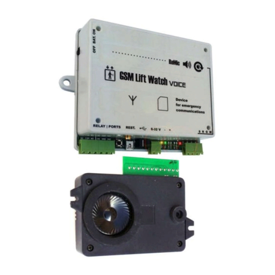
- Page 14 Parts of GSM Lift Watch: Basic unit (GLWV) Speaker module (ReMicA1,L1) Speaker module (ReMicAS1)
- Page 15 Switch for backup ACU Loudness setting SIM card LED indication Screws and PSU LED USB connector USB connector GSM antenna RESET button Ports screw terminal ReMic screw terminal Relay screw terminal (SRGM)
-
Page 16: Led Indicators
Ports (IN1, IN2)and relay screw terminal Blocking input IN2 (short circuit to ground) Shared screw - ground input IN1 Relay contact screw (in stand by open - NO) Shared relay contacts screw (COM) Contact relay screw (in stand by closed - NC) LED indicators PWR - power GSM –... - Page 17 Screw terminal for ReMic (SRGM) Screws for connection to ReMic module in lift cabin – connect same marked screws M – microphone G – ground R – speaker S - signalling Screw terminal of speaker module ReMicA (ReMic) Jumper current limiting of switch (see example examples) Screws of indicator switch I1 Screws of indicator switch I2...
- Page 18 Screw terminal of speaker module ReMicAS1 The module is a variant of ReMicA1 designed for low panel installation (height 22mm) Screws of emergency button Screws for connection to GLWV basic unit – connect together same marked screws (see above) Isolated screws of call activation by voltage 12V Screws of indicator switch I1 Screws of indicator switch I2...
- Page 19 speaker and MIC are installed toward to lift cabin Fixing of REMIC at back side of lift cabin (button panel) (for example by screws) ReMicA/L1...
- Page 20 ReMicAS1 Fix the GSM part of unit either on lift cabin or in machine room. You have to select right place regards to GSM signal strength. Lift cabin installation is easier (it is not necessary cable from lift cabin to machine room and due this is avoid of interference).
- Page 21 Screw up antenna cable connector. The antenna position must not be in space surrounding by metal (metal shafts etc.) It caused reduction of GSM signal. When you connect magnetic antenna please put it to some bigger iron subject. which enables to create bigger GSM signal power. It is also important to place antenna out of basic unit to not interference the voice channel by GSM radiation (you know it from radio in car)
- Page 22 Up drawing mentioned above connect ReMic module to basic unit. To the ReMic module connect indication and activation button. Do not connect power supply. At the basic unit do not connect inputs (port) yet. Operation start: When you programme parameters directly to SIM by savings numbers and names please insert SIM into mobile phone and programme it.
- Page 23 When you programme the unit by computer please connect USB cable and follow instructions in appropriate capture. When you programme the unit by SMS and there is not saved any TESTx (x is number 1-8) number on the SIM card please send SMS „INIT TEST1 xxxxxxxx“...
- Page 24 too high you can get different acoustic troubles like acoustic shock, etc. In this case decrease loudness or microphone sensitivity. By called party hanging up end connection with GLWV. I2 (I1) port contacts are opened. On GLWV green LED lights off „connect“...
- Page 25 periodically. The unit can’t log into GSM network. It is either too low GSM signal or antenna is not connected. Blue LED (PWR) lights up, yellow LED is flashing up GSM signal strength. It has been played message „ The unit in stand by mode“.
- Page 26 Bad volume level from lift cabin. Incorrect microphone installation (must be placed directly behind the panel hole) or low level of microphone amplification (via capture Installation).
- Page 27 System programming There are 3 ways of System programming: 1. By savings appropriate numbers (MASTERx eventually TESTx, eventually PARGLWV and PARRL1) to SIM card by mobile phone. 2. Remotely by SMS messages. On the SIM card inserted in the unit must be already programmed number from which we send SMS like TESTx (x is number1 to 8).
- Page 28 (TEST). The line after space it means numbers which are not dialled by unit might be multiple (on the SIM card might be saved 6 numbers under name MASTER4). It means that amount of numbers allowed for incoming calls or programming are limited just by SIM card capacity.
- Page 29 Numbers and names saved on SIM card meaning name operation MASTER1 - first number which is call by GLWV after emergency call activation. When GLWV should emergency functionality this number must be saved on the SIM card. - this number is allowed make incoming calls MASTER2 - when this number is saved the GLWV call him when MASTER1 number is unreachable, busy or doesn’t pick up...
- Page 30 TEST3 - when this number is saved the GLWV call him when TEST2 number is unreachable, busy or doesn’t pick up call a long time - this number is allowed make incoming calls - this number is allowed make remote SMS configuration TEST4 - when this number is saved the GLWV call him when TEST3 number is unreachable, busy or doesn’t pick up call a long...
- Page 31 VOLTAGE - voltage limit. A low voltage SMS is sent when the value falls below this value. AA * B (not set by default - voltage not monitored) AA - Volts [01-24] B - tenths of volts [0-9] - firmware version in GLWV - just info don’t change! SERVICES - date of last service check and number of checks (mode “Service OK”) - just info –...
- Page 32 5 – „servis” mode – after short circuit on IN1 port as mode 4 + sends SMS "SERVICE" to number PORTCLOSE 6 – „running” mode – relay closed, when GLWV operates (voltage, logged in GSM network) CC – closing time [00-99]s D –...
- Page 33 When is programmed some numerical parameter its value is mentioned after colon„:“. When parameter has more digits both digits must be mentioned. For example: WRITE PAR TPERIOD:3 WRITE PAR BLOCK:09 GLWV sends back SMS where is copied inserted command at beginning.
- Page 34 [x=0-9] 0 – function is off WRITE PAR TSHIFT:x Move service call start from midnight [0- 9] x2 hours (i.e. 8= shift 16 hours) WRITE PAR TMODE:x Type of performed tests x=0 – no test x=1 – service call for TESTx numbers x=2 –...
- Page 35 activation as mode 4 + sends SMS "SERVICE" to number PORTCLOSE x=6 – „running” mode – relay closed, when GLWV operates (voltage, GSM network registration) WRITE PAR RL1TMON:yy Closing time in seconds [yy=00-99]s WRITE PORTCLOSE +420cc..c When IN1 is grounded sends SMS to number (according to the settings) : „PORT CLOSE“...
- Page 36 WCALL:30 EMODE:0 RL1MOD:0 RL1TMON:10 Then is just edit this received SMS - „READ“ rewrite it to „WRITE“, erase parameters which you not setup, adjust values of rest parameters and by adjusted SMS sends back as answer to GLWV. The GLWV will mention in answer just adjusted parameters.
- Page 37 GLWV status report: READ STATUS GLWV answer: READ STATUS: VER: 123 BATTERY: 3960mV POWER: 15.5V TIME: “14/09/23,09:21:55” OPER: T-Mobile TEMP: 26C SERV: 14/09/23#126 INP: 0 BLOCK: 0 REL: OFF ECALL:- AKUSTIC: PASS Single parameter saving – setting of waiting time for dialing next number 30 seconds: WRITE PAR WCALL:30 GLWV answer:...
- Page 38 Computer ( PC) programming 1. To preselected directory in PC (for example GLWV) copy from CD program GLWVset. The program is „portable“ – doesn't need installation. In case of need you will be add to same directory sounds files address etc..
- Page 39 mode „ON“ „ON“ mode is identify by switch in position ON To program parameters stop GLWV operation (programming mode) by click to button. Program sends signal to GLWV and wait for answer (shows bargraf – via picture) After a while (GLWV checks signal every 30 seconds) will GLWV switch –...
- Page 40 After click to „Support“ button is possible monitor GLWV operation (when operation is not stop by button „ON/OFF“) Saving of report (log) from monitor to file (for service purposes – report sending)
- Page 41 Programming mode (position OFF) GLWV is signalling programming mode by message „Device in stand by mode“ and permanent light of yellow LED (GSM). Program indicates mode by switch in position „OFF“. All parameters are automatically recorded from GLWV to the program. „EMERGENCY“...
- Page 42 Folder „SERVICE It is designed for service call parameters programming Period of TEST function activation Movement of TESTs start from midnight Test type setting Number for sending status SMS Waiting for connection before dialling next number in order. Overtake from EMERGENCY Field to programm up 7 phone numbers of service call...
- Page 43 Phone Book folder Phone book on the SIM – checking numbers on the SIM – for example: GSM operator, service status (SERVICE) etc…. Name position Phone number position Add line over line with cursor Erase line with cursor Search for inserted name...
- Page 44 „Ports“ folder Relay mode setting Numbers where are send SMS when IN1 port is open and closed When number is not filled SMS is not send Information about mode which influence using type of IN1 port(SMS) Voltage on limit level for decision acceptable/low voltage.
- Page 45 „Support“ folder In „ON“ mode is designed for operation monitor (via „ON“ mode) In „OFF“ mode is designed for upgrade fw, adjustment voice messages and SMS contents. CAUTION! Not expert manipulation might caused unfunctionally of GLWV which is not responsibility of producer. Commands or files list which will be recorded to GLWV (manually editable)
- Page 46 Examples We recommend copy of command examples from CD to directory with PC configuration program. Voice messages substitution by other language from sent file. 1. open the zip file (even with directory) into directory where you have PC configuration program GLWVset. 2.
- Page 47 Voice message substitution by own messages with miss message „emergency communicator of lift“ 1. Zip file VoiceMessages from examples open (even with directory) to directory in which you have PC configuration program GLWVset 2. Files substitute by yours (except file ecall.wav) in the same format (wav, PCM, 8kHz, mono, 8 bits) –...
- Page 48 3. Click on button „Load List“ and in directory select file „EcallMessages.ifo“ – will be shown list of sound messages (here just one – ecall.wav) which will be recorded to GLWV. 4. By click on button „Send“ send file to GLWV (you rewrite current „ecall.wav“...
- Page 49 Return from programming mode to stand by mode „ON“ (again start of GLWV) When all settings is done by press button Save do GDI. GLWV will start again by switching to mode „ON“ – click on button. Program will send signal to GLWV and wait for answer (monitor by bargraf –...
- Page 50 Function Calibrate the acoustic path. If you want to use the Acoustic Path Test function (see settings) and you are using multiple connected ReMic devices, the device has difficult conditions for status recognition (multiple microphones and speakers are connected). In this case, it is necessary to measure the acoustic path in good condition (with the final ReMics positioning and volume setting).
- Page 51 GLWV LED signalling Permanent light Permanent light – weak lighting Blue LED (PWR) Not light Short flashing with period 2 sec. 1 to 5x short flash ▌▌▌ ▌▌▌ ...
- Page 52 GLWV voice messages and tones Besides ordinary tones and signals of GSM communication (ringing tone, busy tone, different operator messages), has GLWV own operation signals. Trill up medium height tone High tone once after number dialing ...
- Page 53 Message block.wav: „Emergency call is blocked. Try again later please.“ Message ecall.wav: „Emergency communicator of lift.“ Message endcall.wav: „Call is terminated.“ Message error.wav: „ERROR“ Message nocall.wav: „Connection failed. Try again later please.“ ...
- Page 54 GLWV with backup ACU When you have GLWV with backup ACU already integrated before installing and operation start check if ACU switch is in down position (off). Do not store unit with ACU when ACUswitch is not in down position! By self discharging might be ACU destroyed without warranty.
- Page 55 When ACU polarity is incorrect flash or light permanently red LED. When all is correct then connect power supply and move switch to up position. – By this connect ACU into system. Test ACU operation by disconnecting of main power supply. We not provide warranty for damages caused by incorrect progress of ACU connection.
- Page 56 Simplest connection ReMicA1 without optical signalling signalling in lift cabin by voice only, power supply from lift system. Emergency button 8-30V...
- Page 57 Simplest connection ReMicAS1 without optical signalling The schematic is the same as on the previous page. Because it is completely identical, the other examples that will be for ReMicA1 also apply to ReMicAS1. ReMicAS1 terminal block Emergency button 8-30V...
- Page 58 Basic connection ReMicA1 with signalling bulbs power supply from lift system. Jumpers closed +/- 12-24V +/- 12-24V Emergency button ReMicA1 8-30V...
- Page 59 Basic connection ReMicA1 with signalling LEDs power supply from lift system. 12-24V Jumpers opened 12-24V Emergency button ReMicA1 8-30V...
- Page 60 Basic connection ReMicA1 with controlling of signalling logic inputs table in the cab (to ground) power supply from lift system. TABLE Jumpers closed Emergency button ReMicA1 8-30V...
- Page 61 Basic connection ReMicL1 with signalling LEDs power supply from lift system. (ReMicL1 is intended only for direct LED connection) Upper jumpers closed in trio Emergency button ReMicL 8-30V...
- Page 62 Basic connection with main power supply +/- 12-24V +/- 12-24V Emergency button ReMicA1 Main PSU 230 Vac / 12Vdc...
- Page 63 Connection example with external ACU and charger (Of course, the device may include a built-in backup battery - see technical parameters) +/- 12-24V +/- 12-24V Emergency button ReMicA1 Pb ACU 12V/7 Ah Main Pb ACU charger 12V/700mA...
- Page 64 Connection example for lift cabin – machine room (PREPOJ) communication Lift cabin communication - + 12-24V ReMicA1/ReMicL1 PREPOJ Machine room communication 8-30V...
- Page 65 Connection example for communication lift cabin – shaft – machine room (totally possible connect 3pcs ReMic) Lift cabin communication ReMicA1/L1 - + 12-24V Lift shaft communication PREPOJ 2x ReMicB Machine room communication 8-30V...
- Page 66 Connection example of activation by galvanically isolated screws of switch 12V ReMicA(L)1 – connection to bell or siren. Siren connection example in relay mode „button“ (Relay closed during button press) 12-24V (according siren)
- Page 67 Connection example of „service“ button with pilot light of „confirmation“ (Pilot light will lights up when GLWV receive „service“ button press and send SMS) Button “service” 12-24V (according pilot light)
- Page 68 Alphatech spol. s r.o. Jeremenkova 88 140 00 Praha 4 tel. +42 0 272 103 335, fax. +42 0 272 103 334 e-mail: info@alphatech.cz internet: http://www.alphatech.cz naše souřadnice GPS (WGS 84) N 500235.5 E 142542.0 24.8.2020...
Need help?
Do you have a question about the GSM Lift Watch Voice and is the answer not in the manual?
Questions and answers