Advertisement
ISO 9001:2015 Certified Company
"DMTech" Ltd., Pleven, Bulgaria, 16 "Nikolay Haytov" Str., Tel. +359 64 801 597
e-mail:
office@dm-teh.com
"DMTech" Ltd. Pleven
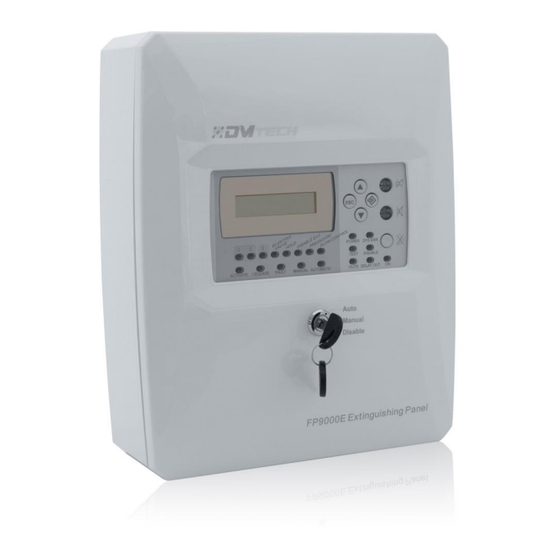
Extinguishing Control Panel
FP9000E
INSTALLATION
AND OPERATION MANUAL
Rev 04:19
Tel./Fax : +359 64 801 597
e-mail
:
office@dm-teh.com
web
: www.dm-teh.com
Address
: Pleven,Bulgaria 5800
16 "Nikolay Haytov" Str.
,
Page 1 of 19
Advertisement

Subscribe to Our Youtube Channel
Related Manuals for DMTech FP9000E

Summary of Contents for DMTech FP9000E
- Page 1 Address : Pleven,Bulgaria 5800 16 “Nikolay Haytov” Str. "DMTech" Ltd. Pleven Extinguishing Control Panel FP9000E INSTALLATION AND OPERATION MANUAL Rev 04:19 “DMTech” Ltd., Pleven, Bulgaria, 16 “Nikolay Haytov” Str., Tel. +359 64 801 597 Page 1 of 19 e-mail: office@dm-teh.com...
-
Page 2: Table Of Contents
FP9000E has 3 zones - 2 extinguishing with activation of automatic fire detectors and 1 conventional fire zone. Automatic and manual operation modes (selectable via 3 positional key lock) allow the operators to choose the extinguishing process control. -
Page 3: Technical Parameters
Instructions for installation, setup and operation - FP9000E 2. TECHNICAL PARAMETERS Fire LINES Lines: Extinguishing–2 fixed lines (Line 1 and Line Fire Alarm – 1 fixed line (Line 3) Maximum number of fire detectors in a line ... - Page 4 Instructions for installation, setup and operation - FP9000E Electrical characteristics 24 VDC/ 0,5A EXT (Extinguishing, EN 12094-1) – Monitored: Type potentional relay 24 VDC/1.5A 15min Electrical characteristics 24 VDC/3A 100ms Adjustable time triggering the output of 5 to programmable 900 seconds.
- Page 5 Instructions for installation, setup and operation - FP9000E Type of the battery Lead, gel Battery rated voltage 12V DC Reted power C20 5 (4.5)Ah Internal resistance of the accumulator battery Ri: < 0.3Ω temperature Charger voltage...
-
Page 6: Controls And Indication
Instructions for installation, setup and operation - FP9000E EN 54-2:1997/AC:1999 EN 54-4:1997 EN 54-4:1997/A1:2002 EN 54-4:1997/A2:2006 EN 54-4:1997AC:1999 EN 50130-4:2011 EN 55022:2006/А1:2007 EN 60950-1:2006/А11:2009 3. CONTROLS AND INDICATION LED indicators Indicators Function “POWER”... - Page 7 Instructions for installation, setup and operation - FP9000E Individual indicators for line failure. When disabled and line test there is “1 2 3” yellow an indication of the respective condition. BUTTONS Access Действие на органа за управление Button Panel condition level “RESET”...
-
Page 8: Default Parameters
Instructions for installation, setup and operation - FP9000E 4. DEFAULT PARAMETERS The fire panel provides users with default parameters, described in the table below. These parameters are saved and recorded from menu "Default par.". Fire Lines Current thresholds in the Fire lines: ... - Page 9 5.2 A description of the PCB terminals The FP9000E panel is mounted on a plastic chassis at the bottom of the panel. The connections to the main power unit, indication board and earth points are factory mounted. The connection wires for zones and control devices must be run out through the opening above the terminal rows.
- Page 10 Instructions for installation, setup and operation - FP9000E drops). The active state of the input, NC (Normal closed) or NO (Normal open), can be configured through the panel setup menu. Rel 1ST (NO/COM) – Dry contact relay output. The relay is activated in case of Fire Alarm Stage 1 operation mode.
- Page 11 Instructions for installation, setup and operation - FP9000E Fig.2 One line can allow the installation of up to 32 Fire detectors generally, regardless of their type. To the unused lines, directly to the terminals mount the final element "EOL", otherwise the lines will be able in Fault condition.
- Page 12 Instructions for installation, setup and operation - FP9000E sounders that could be connected in the circuit depends on their total current consumption, which must not exceed 0.5A. Before connecting the last sounder in the circuit, parallel to it must be added resistor 4.7k.
- Page 13 Instructions for installation, setup and operation - FP9000E Fig. 5 – Example of wiring a solenoid 5.7 Connecting the OC Outputs The open collector outputs are used for connecting external devices. The OC1, OC2, OC3, OC4, OutFire and Fault has same functionality and characteristics. The internal structure and an examples are shown on Fig.
- Page 14 If necessary, adjusts the clock for real-time of the panel. Reset archive events. 7. LEVELS OF ACCESS In panel FP9000E there are 4 LEVELS of access to the various indications and control functions. Access Level 1 This level of access is for all persons, whom can be expected to identify and react to Fire alarm, Activated or fault.
-
Page 15: Access Levels
Instructions for installation, setup and operation - FP9000E This is a level of access to persons, who are responsible for the safety and are trained and authorized to operate the panel in the conditions: Security; Activated; Fire;... - Page 16 Instructions for installation, setup and operation - FP9000E The extinguishing panel is in normal operation mode (stand-by) when only the LED “POWER ON” on the front power is lighting on in green. The internal buzzer and all other status LEDs are off. The key for selection of the extinguishing mode is set to Automatic, Manual or Disabled position.
- Page 17 Instructions for installation, setup and operation - FP9000E The extinguishing in the site starts after Fire Alarm Stage 2 is over and the set EXTINGUISHING DELAY TIME is out. Then the “Exhting” output on the PCB is activated for a preset EXTINGUISHING DURATION TIME.
-
Page 18: Information And Control Condition
Instructions for installation, setup and operation - FP9000E "on" and "off", respectively for disabled function on and off. The forbidden line is off (not supplied) and it is not controlled for activated Fire alarm and Fault. The disabled controllable output is switched off (the executive device can not be activated) and is not monitored for failure. - Page 19 Instructions for installation, setup and operation - FP9000E - View all the zones in Fire; - View all the failures; - Change the access level from 1 to 2 and vice versa; - Review and launch (at access level 2) of the Disable condition;...
- Page 20 The requirements for operation conditioned in this instruction were met; Defects are not caused by natural phenomena and accidents of thr plug socket. DMTech wishes you splendid work! For any questions may contact the company's technical staff DMTech, by email. e-mail :office@dm-teh.com...
Need help?
Do you have a question about the FP9000E and is the answer not in the manual?
Questions and answers