Table of Contents
Advertisement
®
Installation, Operation and Maintenance Manual
Please read and save these instructions for future reference. Read carefully before attempting to assemble, install,
operate or maintain the product described. Protect yourself and others by observing all safety information. Failure
to comply with these instructions will result in voiding of the product warranty and may result in personal injury
and/or property damage.
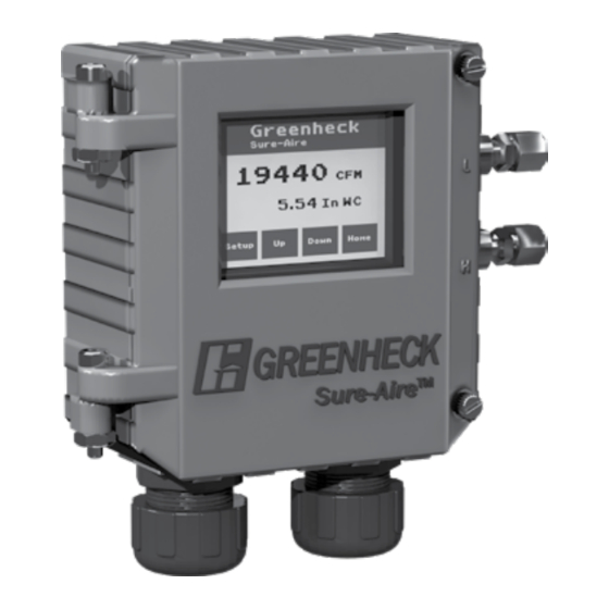
Sure-Aire™ Electronics Features:
• LCD display with user-friendly touch panel interface
• NEMA-4 / IP56 enclosure rating
• Factory calibrated
• Programmable elevation
• English or metric readings
• 24 VAC / DC or 100-240 VAC 50 / 60 Hz input voltage
• Part numbers and pressure ranges:
386719 – 0-4.15 in. wg
386720 – 0-8.30 in. wg
386721 – 0-22.14 in. wg
386722 – 0-41.52 in. wg
386723 – 0-83.14 in. wg
386724 – 0-138.40 in. wg
Pressure ranges reflect differential pressures between
the fan inlet and inlet cone, not system static
pressure.
• Isolated output, linear to differential pressure or
volume
4-20 mA
2-10 VDC
• Communication protocols
BACnet MSTP
Modbus
• Temperature compensation for air density
®
User and Service Manual
Tools Required
•
Four (4) #8-32 screws
•
1/4-inch nylon tubing (length dependent on
distance between fan and Sure-Aire electronics,
maximum 75 feet (23 m) each line)
•
Sensor wiring for temperature sensor (if
temperature sensor is being used)
Flow Accuracy – Within + / - 3.0% of actual flow
Transducer in Electronics
•
Accuracy +/- 0.5% of full scale at 77ºF (25ºC)
•
Pressure limit: 70 psi (1938 in. wg)
•
Thermal effects: 0.015%/°F (0.027%/°C) from -13°
thru 185°F ( 25° thru 85°C)
WARNING
Improper installation, adjustment, alterations,
service or maintenance may cause injury and / or
property damage, as well as possibly void the
factory warranty. No person may install, operate,
or maintain a Sure-Aire™ electronics without first
being fully trained and qualified in the installation,
operation and maintenance, and carefully reading and
understanding the contents of this manual. If you have
any questions about these instructions, contact your
local representative.
CAUTION
Risk of electrical shock! More than one disconnect
switch may be required to de-energize the equipment
before servicing.
Label Information
Sure-Aire™ Flow Monitoring System
Document 1021624
Sure-Aire™ Electronics
1
Advertisement
Table of Contents

Related Manuals for Greenheck Sure-Aire 386719

Summary of Contents for Greenheck Sure-Aire 386719
- Page 1 Document 1021624 Sure-Aire™ Electronics User and Service Manual ® Installation, Operation and Maintenance Manual Please read and save these instructions for future reference. Read carefully before attempting to assemble, install, operate or maintain the product described. Protect yourself and others by observing all safety information. Failure to comply with these instructions will result in voiding of the product warranty and may result in personal injury and/or property damage.
-
Page 2: General Information
General Information This instruction manual provides installation, operating, maintenance, and other information for the Sure-Aire™ electronics. Receiving Upon receiving the electronics, check to ensure all items are accounted for by referencing the packing list. Inspect each crate or carton for shipping damage before accepting delivery. Alert the carrier of any damage detected. The customer will make notification of damage (or shortage of items) on the packing list and all copies of the bill of lading which is countersigned by the delivering carrier. -
Page 3: Wiring Diagram
Installation (continued) 4. Optional Wiring Connections: 4.1 Analog Output Signal: Both 4-20mA and 2-10VDC are available. Connect signal wire into corresponding terminals on block TB3. If using 4-20 mA, a load resistor between 200 and 900 ohms is required, field supplied. If two or more outputs share a common connection, a signal isolator may be required. -
Page 4: Navigation Buttons
“Home” will change to “Edit”). Pressure Units: Press “Edit“ to change pressure units. Home Screen Press “Prev“ or “Next“ to adjust, then press “Enter“ to store the value. Greenheck • In. wg (default) • Ft wg Sure-Aire V 2.00 • mm wg •... -
Page 5: Modbus Rtu Slave
• Yes (saves current settings as the customer default) Network Protocol - Optional Greenheck’s Sure-Aire™ electronics has the ability to connect to a customer’s Building Automation System (BAS) through the on-board RS-485 port. The electronics can be configured as either BACnet MS/TP or Modbus RTU Slave. - Page 6 Analog Output Signal - Optional Greenheck’s Sure-Aire™ differential pressure electronics provides either a 2-10 VDC or 4-20 mA analog output signal. The output signal can be configured linearly proportional to either the pressure range or the flow within the setup. The ranges for Greenheck’s Sure-Aire™ electronics are listed by model on cover.
-
Page 7: Recalibration Procedure
Recalibration Procedure The electronics are calibrated per order at the factory. Under certain circumstances, there may be a discrepancy of calibration once installed on site. The following procedure is used to re-calibrate the pressure trandsucer within the electronics. In the event an error occurs trying to re-calibrate, the tranducer parameters can be re-set to factory settings using “Load Factory Settings”... -
Page 8: Our Commitment
As a result of our commitment to continuous improvement, Greenheck reserves the right to change specifications without notice. Product warranties can be found online at Greenheck.com, either on the specific product page or in the literature section of the website at Greenheck.com/Resources/Library/Literature.
Need help?
Do you have a question about the Sure-Aire 386719 and is the answer not in the manual?
Questions and answers