Table of Contents
Advertisement
Quick Links
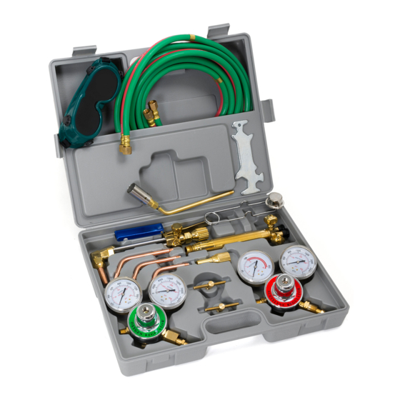
WELDING CUTTING TORCH KIT HARRIS TYPE
ITEM: 55148
OWNER'S MANUAL AND SAFETY INSTRUCTIONS
SAVE THIS MANUAL: KEEP THIS MANUAL FOR SAFETY WARNINGS, PRECAUTIONS, ASSEMBLY,
OPERATING, INSPECTION, MAINTENANCE AND CLEANING PROCEDURES. WRITE THE PRODUCT'S
SERIAL NUMBER ON THE BACK OF THE MANUAL NEAR THE ASSEMBLY DIAGRAM (OR MONTH
AND YEAR OF PURCHASE IF PRODUCT HAS NO NUMBER).
FOR QUESTIONS PLEASE CALL OUR CUSTOMER SUPPORT: (909) 628 4900 MON-FRI 9AM TO 3PM PST
Advertisement
Table of Contents

Subscribe to Our Youtube Channel
Summary of Contents for Stark 55148
- Page 1 WELDING CUTTING TORCH KIT HARRIS TYPE ITEM: 55148 OWNER’S MANUAL AND SAFETY INSTRUCTIONS SAVE THIS MANUAL: KEEP THIS MANUAL FOR SAFETY WARNINGS, PRECAUTIONS, ASSEMBLY, OPERATING, INSPECTION, MAINTENANCE AND CLEANING PROCEDURES. WRITE THE PRODUCT’S SERIAL NUMBER ON THE BACK OF THE MANUAL NEAR THE ASSEMBLY DIAGRAM (OR MONTH AND YEAR OF PURCHASE IF PRODUCT HAS NO NUMBER).
-
Page 2: Important Safety Information
IMPORTANT SAFETY INFORMATION GENERAL SAFETY WARNINGS Read all safety warnings and instructions. Failure to follow the warnings and instructions may result in electric shock, fire and/or serious injury. Save all warnings and instructions for future reference. SAFETY The warnings, precautions, and instructions discussed in this instruction manual cannot cover all possible conditions and situations that may occur. - Page 3 IMPORTANT SAFETY INFORMATION Remove keys or wrenches before connecting the tool to an air supply, power supply, or turning on the tool. A wrench or key that is left attached to a rotating part of the tool may cause personal injury. Check for damaged parts before each use.
- Page 4 IMPORTANT SAFETY INFORMATION Make sure you are prepared to begin work before opening gas supply. ALWAYS use reverse-flow on the torch and regulator. This greatly reduces the possibility of mixing gases in the regulator or hose. Use with oxygen and acetylene only. DO NOT modify this torch or use it for a purpose for which it is not intended.
-
Page 5: Assembly And Operation
ASSEMBLY AND OPERATION PRODUCT SPECIFICATIONS ASSEMBLY AND OPERATING PROCEDURES NOTE: The following instructions are for acetylene gas use only. DO NOT use other fuel gases. 1. While standing on one side, “crack” each cylinder valve. “Cracking” is to quickly open and close the valve, allowing gas to escape and clearing the valve of any foreign material. - Page 6 ASSEMBLY AND OPERATION 3. IMPORTANT: The pressure adjusting screw (18) on the acetylene regulator and the pressure adjusting screw (A18) on the oxygen regulator should be turned counter-clockwise to relieve pressure on the regulator diaphragms before opening the cylinder valves. If this is not done, pressure form the cylinders may damage the diaphragms and render the regulators inoperable.
-
Page 7: Checking For Leaks
CHECKING FOR LEAKS 1. After everything is connected, close both Torch Handle Valves, turning clockwise. Close Regulators, turning knobs counter-clockwise until loose. 2. Open the cylinder valves turning counter-clockwise only until the gas starts flowing. WARNING! Only open Acetylene Cylinder Valve 1/4 to 1/2 turn. 3. - Page 8 CHARTS NEVER set the Acetylene Regulator (Parts 1-19) to a delivery pressure above 15 PSI. See figures I, J and K WELDING TIP CHART FIGURE I OXYACETYLENE MULTI-FLAME HEATING CHART FIGURE J OXYACETYLENE CUTTING NOZZLE CHART FIGURE K 9. To determine the proper acetylene regulator parts (parts 1-19) pressure and oxygen regulator (parts A1-A20E) pressure for neutral flame adjusting.
-
Page 9: Operation
OPERATION HIGH PRESSURE OXYGEN CONTROL LEVEL (C20) VALVE (B8) FIGURE L CUTTING NOZZLE (D6) PRE-HEAT OXYGEN ACETYLENE CONTROL VALVE CONTROL VALVE (C26) (B10) 12. Open the acetylene control valve (B8 with AC label (B10) on the torch handle. Adjust the acetylene regulator (parts 1-19) to the desired working pressure. -
Page 10: Inspection, Maintenance And Cleaning
MAINTENANCE 17. Once the welding or cutting job is completed, turn off the oxygen control valve (B8 with OX label B9) Then turn off the acetylene control valve (B8 with AC label B10) NOTE: Reversal of this procedure may cause damage to the torch handle (parts B1-B10. See figure N 18. -
Page 11: Parts List
PARTS LIST ACETYLENE REGULATOR PARTS LIST NOTE: Some parts are listed and shown for illustrations purposes only and are not available individually as parts. - Page 12 PARTS OXYGEN REGULATOR PARTS LIST NOTE: Some parts are listed and shown for illustrations purposes only and are not available individually as parts.
- Page 13 PARTS TORCH HANDLE PARTS LIST...
- Page 14 PARTS CUTTING ATTACHMENT PARTS LIST...
-
Page 15: Accessory Parts List
PARTS ACCESSORY PARTS LIST... -
Page 16: Warranty
WARRANTY PLEASE READ THE FOLLOWING CAREFULLY THE MANUFACTURER AND/OR DISTRIBUTOR HAS PROVIDED THE PARTS LIST AND ASSEMBLY DIAGRAM IN THIS MANUAL AS A REFERENCE TOOL ONLY. NEITHER THE MANUFACTURER OR DISTRIBUTOR MAKES ANY REPRESENTATION OR WARRANTY OF ANY KIND TO THE BUYER THAT HE OR SHE IS QUALIFIED TO MAKE ANY REPAIRS TO THE PRODUCT, OR THAT HE OR SHE IS QUALIFIED TO REPLACE ANY PARTS OF THE PRODUCT.
Need help?
Do you have a question about the 55148 and is the answer not in the manual?
Questions and answers