Table of Contents
Advertisement
Advertisement
Table of Contents

Summary of Contents for Tohnichi R-CM
- Page 1 MODEL: R-CM Operating Instruction To use this product properly and safely, please read this operating instruction carefully before use. If you have any question about the product and its operations, please contact your nearest distributor or Tohnichi Mfg. Co., Ltd.
- Page 2 To customers: Before using this product, please read this operating instruction carefully to use it properly. If you have any question, please contact your nearest distributor or Tohnichi Mfg. Co., Ltd. This operating instruction should be stored in a safe place.
-
Page 3: Table Of Contents
■ Contents 1. Outline 2. Specifications 3. External View and Each Part Name 3-1. Figure and Name of Parts for T-FH/T-FHM and previous transmitters 3-2. LCD Display 3-3. RS232C Connector 3-4. In/Output Connector and LED 4. Precauton for Use 4-1. Power Source 4-2. -
Page 4: Outline
This R-CM applied interchangeable radio modules and by attaching a Tohnichi radio module, it can be used as various Tohnichi wireless Pokayoke receiver. This makes it easy to update the receiver from a standard tightening counting type error proofing torque wrench system to data transmission type torque wrench by changing the radio module of receiver. -
Page 5: External View And Each Part Name
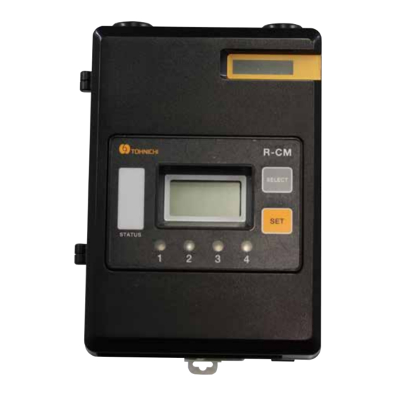
External View and Each Part Name 3-1. Figure and Name of Parts for T-FH/T-FHM and previous transmitters Front Cover Module Fixing Lever Status Lamp SELECT button SET button Receive LED Power Terminal Extension Connector In/Output Terminal Locker RS232C Connector Power Switch ●... - Page 6 ● Input/Output terminal Terminals for output, reset and LS input of tightening completion signal or OK/NG judgment result. *The operations depend on the radio module. For details, refer to the instruction manual for each wireless module. ●Power switch On/Off the power ●...
-
Page 7: Lcd Display
3-2. LCD Display 1. M-FH or M-BL radio module with OFF the count checker function. Operation mode: [ID] Setting mode: Setting Items Battery Level of Transmitter Operation mode: Receiver’ s ID Setting mode: Displays setting value 2. M-FH or M-BL radio module with ON the count checker function. Operation mode:[COUNT] Setting mode: Displays each setting item Transmitter’... -
Page 8: Rs232C Connector
Signal Detail Direction Transmitted data signal Received data signal Ground Clear to send signal Request to send signal 2. R-CM and PC/PLC Connection Cable, Example R-CM: D-Sub9S Female PC/PLC: D-Sub9S Female PIN # Signal Name Detail PIN # Signal Name... -
Page 9: In/Output Connector And Led
3-4. In/Output Connector and LED Receive LED3 Receive LED4 Receive LED1 Receive LED2 Pin No. Terminal Function Completion signal type: Output a relay signal when receive the same ID signal set at OUT1. Data transfer type: OUT1 When the tightening torque value from the wrench registered in ID1 is within the set Hi/Lo limit values, a signal outputs from OUT1. - Page 10 Terminals for Count Checker function [INPUT TERMINAL] ● END Input terminal: IN2 Input terminal for work end signal. By connecting it to COM terminal via 0.1 seconds or more of contact relay signal generated by a push button switch, PLC etc., pass/fail judgment is performed based on the remaining count at that time. ●...
-
Page 11: Precauton For Use
Caution ] ! Be sure to use 24 V DC for the R-CM power supply. * An optional AC adapter BA-8R is required to use AC100V - 240V power source * Tightening torque of terminal screws are T = 50cN • m. - Page 12 4-3-1. Caution of Input Connector Internal Circuit ● IN1 and IN2 Input terminal Photo coupler EMI filter No-voltage contact switch EMI filter Photo coupler No-voltage contact switch Internal circuit Connect this input terminal with a non-voltage contact switch such as LS torque wrench, push button switch, or relay.
- Page 13 4-3-3. Contact Protection Circuit When the inductive load is opened or closed, a counter-electromotive voltage is generated. This could cause a heavy damage to the contact, resulting in a significant shortening of operating life. Therefore, a contact protection circuit is required. The examples of contact protection circuits are shown in the table below. Apply Feature Selection of Elements...
-
Page 14: Handling
Handling 5. How to Use 5-1. Installation/Remove way of the Radio Module 5-1-1. How to Install the Radio Module to Receiver * Be sure to attach the antenna to the radio module before mounting the module on receiver. 1. Open the front cover of receiver and fit the module to the board. - Page 15 5-1-2. How to Remove the Radio Module from Receiver 1. Release the metal fittings that fixes into the grooves of the module, and pinch and lift the sticker of the radio module. * Do not lift forcibly before release the metal fittings, the levers may caused deformation.
-
Page 16: How To Attatch On Din Rail
● 35mm width DIN rail * R-CM standard accessory * Should be attached R-CM on the DIN ral and install the extension BOX IO-CM and BZ-CM. 1. Pull out the white rocker on the R-CM in the direction of the arrow until it clicks into place. Locker 2. - Page 17 5-2-2. How to remove from DIN rail 1. Pull out the white rocker on the R-CM in the direction of the arrow until it clicks into place. Locker 2. Pull the R-CM main body in the direction of the arrow and remove it from the DIN rail.
-
Page 18: How To Replace The Backup Battery
- Torque driver, e.g. RTD60CN - Plus bit #2 catalog No..86 1. Make sure that the R-CM is turned off, and remove the radio module referring to “5-1-2. 2. Loosen the three screws on the back of the case and remove the case lid. - Page 19 Tightening torque = 32cN . m 5. Since the current time will bes reset, set the clock again by using the parameter setting software. - FHM/FH manual 8-2. Setting Software - FD/FDD manual 12. R-CM+M-FD Setting by setting software. 19...
- Page 20 ■Tohnichi Shanghai Mfg. Co., Ltd. 东仁扭矩仪器(上海)有限公司 Tel.+86 21 3407 4008 Fax.+86 21 3407 4135 RM.5 No.99 Nong1919, Du Hui Road, Minhang, Shanghai, P.R.China ● All rights reserved. No reproduction or republication without written permission. ● ©Tohnichi Mfg. Co., Ltd. All Rights Reserved. 200.08.19.EN.S...
Need help?
Do you have a question about the R-CM and is the answer not in the manual?
Questions and answers