Advertisement
SNAP PAC Rack Adapter Installation
Introduction
SNAP PAC racks are designed to be used with SNAP PAC brains and
rack-mounted controllers. However, if you have an older I/O
processor that you need to use with a SNAP PAC rack, the SNAP-
RCK-B2M rack adapter makes it possible. The adapter can also be
used with SNAP M-series racks to accommodate processors that
would normally be used on a B-series rack.
The adapter works with the following part numbers:
Install the adapter to use
one of these processors...
SNAP-UP1-ADS
SNAP-B3000-ENET
SNAP-ENET-RTC
Important Notes
Change in height: The adapter adds 0.595 inches (1.511 cm) to
the overall height of the unit.
Change in connector location: After installation of the adapter,
the brain or controller's position will be reversed on the rack (as well
as being higher in relation to the rack), and letters on the lid will be
upside down. Make sure that cables can still reach the connectors
on the processor.
No new features: The adapter does not change the capabilities of
the brain. For example, four-channel digital modules still cannot be
used in module positions 8 and higher.
Installing the Adapter
Requirements
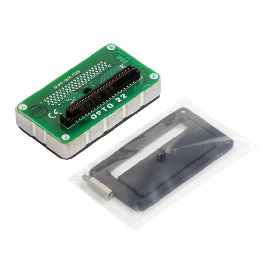
Part number SNAP-RCK-M2B includes the following pieces:
•
Lock washer
•
6-32 hex standoff
•
Replacement baseplate
•
Adapter
...on one of these racks
SNAP-PAC-RCK4
SNAP-PAC-RCK8
SNAP-PAC-RCK12
SNAP-PAC-RCK16
SNAP-M16
SNAP-M32
SNAP-M48
SNAP-M64
You will also need a medium-sized Phillips screwdriver to install the
adapter.
Installation Steps
1. Remove all SNAP-RCK-B2M pieces from their packaging.
2. Turn off power to the rack.
3. If there is already a processor on the rack, disconnect any cables
connected to it. Loosen the screw holding the processor on the
rack and remove the processor. Set it aside.
4. Turn the replacement processor (brain or controller) upside
down. Remove the four small screws holding the black base-
plate on the processor, and remove the baseplate. Keep the
screws.
5. Hold the replacement baseplate so that its indentation is facing
away from the brain (see the following photo).
Hold-down screw
6. Align the brain's hold-down screw with the center hole in the
replacement baseplate. Using the same four screws, attach the
replacement baseplate to the new processor.
7. On the rack, set the lock washer over the hole next to the pro-
cessor's connector, and then screw the 6-32 hex standoff into
the hole. Tighten the standoff just to the position where two of
the hex points are parallel with the connector, as shown in the
photo on the following page.
Indentation
Beveled screw hole
(bevel faces out)
PAGE
1
Advertisement
Table of Contents

Related Manuals for OPTO 22 SNAP-RCK-M2B


Summary of Contents for OPTO 22 SNAP-RCK-M2B
- Page 1 Tighten the standoff just to the position where two of Installing the Adapter the hex points are parallel with the connector, as shown in the photo on the following page. Requirements Part number SNAP-RCK-M2B includes the following pieces: • Lock washer • 6-32 hex standoff •...
- Page 2 SALES 800-321-6786 • 951-695-3000 • FAX 951-695-3095 • sales@opto22.com • SUPPORT 800-835-6786 • 951-695-3080 • FAX 951-695-3017 • support@opto22.com © 2007 Opto 22. All rights reserved. Dimensions and specifications are subject to change. Brand or product names used herein are trademarks or registered trademarks of their respective companies or organizations.
Need help?
Do you have a question about the SNAP-RCK-M2B and is the answer not in the manual?
Questions and answers