Advertisement
Quick Links
Serge Audio Mixer
SERGE Audio Mixer
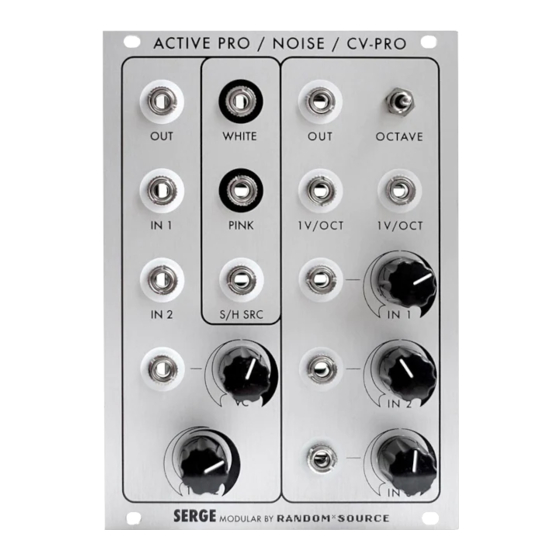
The Serge CV-PRO / MIXER pcb set by Random*Source can be built as either a (single or dual) Voltage Proces-
sor or as an active Audio Mixer with 3 input chanels, where the phase of the first input can be inverted for
phase cancellation effects. This document describes only the Audio Mixer setup.
As the Audio Mixer uses only one half of the main pcb, the areas grayed out in the following picture should
be ignored (left empty):
Please note:
•
Orientation of the main pcb: power header is at the bottom (when looking at the module up-
right, e.g. in a rack).
•
Circuit contains an interesting diode-based limiter section to prevent the added signals from
ugly clipping. This was presumably intended for use of the module as a CV processor. However,
it can also be used with audio signals - this leads so a fairly strong softening / rounding of the
resulting waveform that affects the sound similar to a slight wavefolding.:
For a "clean" audio mixer leave the jumpers JP1 open to ignore the limiter section.
To experience the effect of the limiter section, install 2 jumpers at JP1 (parallel to the board, i.e.
connecting left and right pins in the photo above).
•
Use a nice (dual) op-amp for high fidelity, e.g. a Burr-Brown OPA2134 or Burr-Brown OPA2604.
RANDOM*SOURCE
RANDOMSOURCE.NET
1
Advertisement

Subscribe to Our Youtube Channel
Summary of Contents for Random*Source Serge CV-PRO
- Page 1 SERGE Audio Mixer The Serge CV-PRO / MIXER pcb set by Random*Source can be built as either a (single or dual) Voltage Proces- sor or as an active Audio Mixer with 3 input chanels, where the phase of the first input can be inverted for phase cancellation effects.
- Page 2 RANDOM*SOURCE Serge Audio Mixer Bill of Materials (Audio-Mixer) Resistors 2 10R F1, F2 alt: 22R, FERRIT BEAD 1 220R 1 820R 1 10K 7 100K R1, R2, R3, R4, R6, R7, R21 1 220K Capacitors 1 47pF Mica or TDK C0G...
- Page 3 Mount the component pcb onto the front panel again and screw on the pots from the front side. 10. Make sure everything is in place. 11. Solder the switch in by soldering the air-wires onto the correcponding contacts. 12. Solder the banana jacks in. 13. Attach any screws / spacers if desired and mount the main pcb onto the component pcb. 14. Connect a power cord supplying +12V, GND, GND, -12V to the MTA-header on the main board and you should be ready to go :-) Calibration Module does not require any calibration. (Version 16 Feb 2015) SERGE Modular by Random*Source. Module and circuit under license from Serge Tcherepnin. All rights reserved. RANDOMSOURCE.NET...
Need help?
Do you have a question about the Serge CV-PRO and is the answer not in the manual?
Questions and answers