Table of Contents
Advertisement
TOPAS
E350V – E600V
Oil flooded rotary vane vacuum pump
Translation of the original instructions
briwatec GmbH
Schönauer Str. 62
79669 Zell i. W.
Germany
Telephone no.:
+49 (0) 7625 918 868-0
Fax no.:
+49 (0) 7625 918 868 -33
email:
info@briwatec.de
Website:
www.briwatec.de
Managing Directors: Markus Britsche, Michael Wagner
District court: Freiburg i. Br. HRB 700368
VAT number.: 11088/10922 Value added tax identification-no.: DE 814 742 383
Advertisement
Table of Contents

Related Manuals for briwatec TOPAS Series


Summary of Contents for briwatec TOPAS Series
- Page 1 TOPAS E350V – E600V Oil flooded rotary vane vacuum pump Translation of the original instructions briwatec GmbH Schönauer Str. 62 79669 Zell i. W. Germany Telephone no.: +49 (0) 7625 918 868-0 Fax no.: +49 (0) 7625 918 868 -33 email: info@briwatec.de...
-
Page 2: Table Of Contents
Contents Contents Contents ....................2 Introduction ..................3 2.1 Information about the operating manual ......... 3 2.2 Limitation of liability ..............3 2.3 Copyright ..................3 2.4 Spare parts .................. 4 2.5 Service ..................4 2.6 CE-Declaration of Conformity ............5 Safety .................... -
Page 3: Introduction
GmbH) The agreed contract obligations, general terms and conditions and the delivery conditions from briwatec GmbH apply, as well as the valid legal regulations at the time of signing the contract. We reserve the right to make technical changes in the context of improving the performance characteristics and further development. -
Page 4: Spare Parts
Introduction Reproduction in any shape or form - even in part - and the use and / or commu- nication of content without a written declaration from briwatec GmbH is not per- mitted.. Spare parts The company briwatec GmbH recommends the use of original spare parts. Origi- nal spare parts have special qualities that ensure a reliable and safe operation: ... -
Page 5: Ce-Declaration Of Conformity
Introduction CE-Declaration of Conformity Fig. 1 CE-Declaration of Conformity B125 06/16 Rev.1 TOPAS E350V-E600V... -
Page 6: Safety
Information and warning signs In the event of use that deviates from the proper and intended use, all liability and warranty will be rejected by the company briwatec GmbH. Description of safety instructions Safety instructions refer to specific hazards. They are marked by symbols in this manual. -
Page 7: Safety And Information Signs On The Machine
Safety WARNING! Indicates a potentially hazardous situation that can result in death or serious injury if not avoided. CAUTION! Indicates a potentially hazardous situation that can lead to minor injuries or property damage if not avoided. The following additional information is used in these instructions: NOTE! This symbol indicates an important fact. - Page 8 Safety The symbols placed on the machine refer to the risks and prohibitions explained below. The safety information and recommendations must always be fol- lowed and you must act prudently to prevent accidents involving personal injury and property damage! WEAR HEARING PROTECTION! Mandatory use of noise protection (ISO 3864 / EN 61 310-1)! READ THE INSTRUCTIONS FOR USE! Mandatory reading of the instructions for use (ISO 7000-0419)!
-
Page 9: Personnel Requirements
Safety WARNING! Maintenance work in progress (read instructions!) WARNING! Parts or circuits under high pressure! WARNING! The unit is remote controlled and may start up without a warning signal (ISO 7000-0017)! Personnel requirements WARNING! Danger due to inadequate qualifications. Improper operation may result in considerable personal injury and material damage. -
Page 10: Intended Use
Safety … Construction and operating principle of the machine. Rotary vane Suction power … Volume flow of a vacuum pump in relation to the condition in the suction con- nection. Final pressure (absolute) … the maximum vacuum that a pump achieves with a closed suction opening, indi- cated as absolute pressure. -
Page 11: Improper Operation
Safety Improper operation Misuse may result from the following circumstances: Suctioning, conveying and compressing explosive, combustible, aggressive or toxic media, e.g. dust according to ATEX zones 20-22, solvents and gaseous oxygen and other oxidants. The use of the machine in non-commercial premises, assuming that the necessary precautions and protective measures are not taken on the premises. -
Page 12: Technical Specifications
Technical specifications Technical specifications Type plate The type plate shows the main technical specifications of the device. For technical service consultations, the type description, year of manufacture and serial number must be available. Fig. 3 Type plate Noise emissions The following noise emissions were determined for operation at 50/60 Hz: Average sounds pressure level [dB(A)] Type 50 Hz... -
Page 13: Functional Description
Functional description Functional description Conditions of use The TOPAS E350V – E600V vacuum pumps are designed for use in the commer- cial sector. The safety equipment corresponds to DIN EN 13857 Table 4. The TOPAS E350V – E600V is suitable for the evacuation of closed systems or for a permanent vacuum in the range of 0.5 –... -
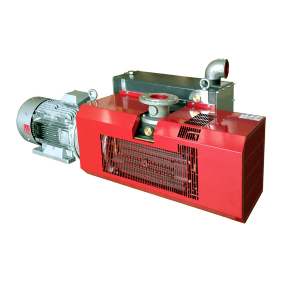
Page 14: Construction
Functional description Construction The TOPAS rotary vane vacuum pump consists of the following major compo- nents: Fig. 4 TOPAS main components Oil filling point Vacuum connection Exhaust air outlet Oil drain valve Oil sight glass Connection for starting discharge (option with magnetic valve) Cooling air inlet Cooling air inlet Motor with direction of rotation arrow... -
Page 15: Function
Functional description Function The pumps of the TOPAS E350V – E600V series are oil-flooded rotary vane vacuum pumps. Fig. 5 TOPAS functional diagram TOPAS E350V – E600V have an oil mist filter on the outlet side. The motor ventilator cools the motor. The motor and pump are connected via a coupling. Accessories: When necessary, a vacuum regulating valve, additional check valve, vacuum-tight suction filter, fluid separator, tube connection, motor circuit breaker and unloader. -
Page 16: Transport Storage
Transport storage Transport storage Safety instructions for transport DANGER! Danger from suspended load Risk of injury or death due to falling loads! Never stand under suspended loads. Maintain adequate distance to suspended loads. Ensure stable centre of gravity. Observe the accident When lifting and transporting the machine, the safety regulations and general prevention regulations! -
Page 17: Commissioning
Commissioning Commissioning Setup The oil filling point, oil sight class and oil outlet must be easily accessible. The cooling air inlet and the cooling air outlets must have a distance of at least 20 cm from the adjacent walls. Emerging cooling air must not be sucked back in again. Fig. -
Page 18: Installation
Commissioning Installation WARNING! Risk of death by electric shock! Unprofessional handling of electrical equipment due to lack of skills can lead to life threatening electric shock. Electrical installation must only be performed by qualified personnel. Protection by means of a main switch must be carried out on site. Vacuum connection, item 2 Fig. -
Page 19: Commissioning
Commissioning Connect the motor and motor protection circuit breaker (for safety, a circuit breaker, and for strain relief of the connecting cable, a cable gland must be provided). We recommend the use of circuit breakers with delayed switch-off according to over-current conditions. -
Page 20: Operation
Operation Operation The average sound pressure level, measured during 50/60 Hz operation, is indi- cated in Chap. 4.2 page 12. Noise emissions: We recommend wearing ear protection when working permanently in the vicinity of the operating pump to prevent damage to hearing. Oil aerosols in exhaust air: Despite the most thorough oil mist separation by the air de-oiling element, the exhaust air still contains small residues of oil aerosols which can be detected by... -
Page 21: Maintenance
Maintenance Maintenance DANGER! Before carrying out maintenance work: For maintenance work, the vacuum pump must be disconnected from the electrical network by unplugging the power cord or by pressing the main switch and securing it against restarting. Do not perform maintenance on a pump that is still warm after operating (risk of injury from hot machine parts or hot lubrication oil). -
Page 22: Fig. 8 Changing The Oil
Maintenance ATTENTION! Pump damage! The use of unsuitable oil can lead to the destruction of the pump. With the use of unsuitable oils, you and/or your supplier bears the responsibility. Only use the oil listed here with the indicated specification! Performing the oil change: Switch off the pump and leave it to cool down. -
Page 23: Changing The Oil Filter
Maintenance Changing the oil filter Only change the oil filter with the pump emptied. To do so, unscrew the old oil filter (item 1) and insert the new oil filter. Fig. 9 Oil filter The oil filter must be changed on every oil change. Filter element / air de-oiling element The filter element becomes contaminated less or more quickly depending on the level of contamination of the suctioned medium. -
Page 24: Fig. 11 Filter Element
Maintenance INFORMATION! Excessive contamination of the filter element leads to pressure loss. The pump performance decreases, and the current consumption of the motor and the pump temperature increase. The filter element may therefore be damaged. Result: Smoke formation from the outlet side! Removal: Fig. -
Page 25: Suction Grid
Maintenance Suction grid A suction grid is located at the inlet of the pump (1). Depending on the level of contamination of the suctioned air, it must be washed or blown out at regular in- tervals. Replace it when necessary. Fig. -
Page 26: Lip Seals
Maintenance Lip seals The outlets of the rotor shaft are sealed with lip seals. The wear on these differs according to the conditions of use. Wear is shown by oil loss or impairment of the final vacuum due to air ingress. The lip seals (1) run on a protective shaft sleeve (2). -
Page 27: Gas Ballast (Optional)
Maintenance Gas ballast (optional) The gas ballast is equipped with an air filter that must be replaced at every oil change. Fig. 15 Gas ballast Removal: Remove the cap (1), Replace the filter element (2). Automatic oil back-suction Fig. -
Page 28: Oil Level Monitoring (Optional)
Maintenance INFORMATION! The oil back-suction sucks the oil collected in the filter element back into the pump. Fig. 17 Float switch for oil back-suction CAUTION! Risk of injury from spraying substances. Wear protective goggles when performing the functional check of the oil back- suction. -
Page 29: Maintenance Intervals
Maintenance Fig. 18 Oil level monitoring INFORMATION! During assembly, ensure the sealing of the thread. 9.11 Maintenance intervals Daily maintenance: Checking of the oil level; see Fig. 8 page 22. Monthly maintenance: Check the pipelines and screw fitting for leaks and solid attachment, and reseal/retighten if necessary. -
Page 30: Troubleshooting
Troubleshooting Troubleshooting 1. Vacuum pump is switched off by motor circuit breaker: Cause Remedy Mains voltage / frequency does not match the motor Adjust the mains network. data. Connection to motor terminal board or to plug is Check the connection or plug connection. incorrect. - Page 31 Troubleshooting 5. Exhaust air contains a visible oil mist: Cause Remedy An unsuitable oil is being used. Check the oil viscosity and type. The air de-oiling element is contaminated. Replace the air de-oiling element. The counterpressure for conveying away the vacuum Optimize the air removal.
-
Page 32: Index Of Figures
Index of figures Index of figures Fig. 1 CE-Declaration of Conformity Fig. 2 Safety and information sign Fig. 3 Type plate Fig. 4 TOPAS main components Fig. 5 TOPAS functional diagram Fig. 6 Structural diagram ...
Need help?
Do you have a question about the TOPAS Series and is the answer not in the manual?
Questions and answers