Table of Contents
Advertisement
Quick Links
Advertisement
Table of Contents

Related Manuals for ADB Safegate SCO

Summary of Contents for ADB Safegate SCO
- Page 1 Series Cutout (SCO) Instruction Manual 96A0294, Rev. H, 7/19/17...
- Page 2 Where applicable, per FAA EB67(applicable edition), ADB SAFEGATE L858(L) Airfield Guidance Signs are warranted against electrical defects in design or manufacture of the LED or LED specific circuitry for a period of 4 years. ADB SAFEGATE LED light fixtures (with the exception of obstruction lighting) are warranted against mechanical and physical defects in design or manufacture for a period of 12 months from date of installation;...
- Page 3 ADB SAFEGATE cannot be held responsible for injuries or damages resulting from non-standard, unintended uses of its equipment. The equipment is designed and intended only for the purpose described in the manual. Uses not described in the manual are considered unintended uses and may result in serious personal injury, death or property damage.
- Page 4 This manual could contain technical inaccuracies or typographical errors. ADB SAFEGATE BVBA reserves the right to revise this manual from time to time in the contents thereof without obligation of ADB SAFEGATE BVBA to notify any person of such revision or change.
-
Page 5: Table Of Contents
2.1 :About this manual ............................5 2.1.1 :How to work with the manual .........................5 2.1.2 :Record of changes .............................5 2.2 :SCO Introduction ............................5 2.2.1 :SCO Cutout: Required Equipment .........................8 2.3 :Specifications ............................... 9 2.4 :Installation ..............................10 2.4.1 :Introduction ...............................10 2.4.2 :Unpacking ................................10... - Page 6 Series Cutout (SCO) 96A0294 Rev. G © ADB Airfield Solutions All Rights Reserved...
-
Page 7: Safety
It is the responsibility of the company operating this equipment to ensure that its personnel meet these requirements. ALWAYS USE REQUIRED PERSONAL PROTECTIVE EQUIPMENT (PPE) AND FOLLOW SAFE ELECTRICAL WORK PRACTICE. © ADB Safegate All Rights Reserved... -
Page 8: To Use This Equipment Safely
Failure to follow these warnings may cause the fasteners to loosen, damage the equipment, potentially to loosen the equipment. This can lead to a highly dangerous situation of FOD, with potential lethal consequences. 96A0003 Rev. C AM.01.001e Edition 1.0 © ADB Safegate All Rights Reserved... - Page 9 • Verify that the moving equipment is rated to handle the weight. • When removing equipment from a shipping pallet, carefully balance and secure it using a safety strap. Failure to follow these instructions can result in death, serious injury, or equipment damage. © ADB Safegate All Rights Reserved...
- Page 10 • Do not attempt to service electrical equipment if standing water is present. Use caution when servicing electrical equipment in a high- humidity environment. • Use tools with insulated handles when working with airfield electrical equipment. Failure to follow these warnings will result in death or equipment damage. 96A0003 Rev. C AM.01.001e Edition 1.0 © ADB Safegate All Rights Reserved...
-
Page 11: Introduction
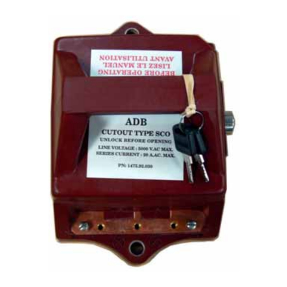
2.0 Introduction A series cutout (SCO) isolates the series circuit from the constant current regulator (CCR) during maintenance or testing operations. It allows periodic insulation resistance measurement of the series circuit to ground without disconnecting the series cable. ADB’s SCO is patented under U.S. patent number 5952737. - Page 12 Series Cutout (SCO) SCO Introduction See Figure 2 for an exploded view of the SCO cutout. Figure 2: SCO Cutout (Exploded View) 1. Cover 2. Body 3. Insulation Measurement Socket 4. Lock and Key 5. Interlock Switch (Located Inside Cutout) 6.
- Page 13 See Figure 3. The handle of the SCO cutout can be rotated to any of three positions to allow different functions. Refer to Table 1 for the three positions of the SCO cutout. Figure 3: SCO Cutout Positions (Activated) Interlock Switch...
-
Page 14: Sco Cutout: Required Equipment
Series Cutout (SCO) SCO Introduction 2.2.1 SCO Cutout: Required Equipment Table 2: Required Equipment Supplied Description Quantity SCO cutout with two keys Instruction manual Handle Position decal Read Manual decal 96A0294 Rev. G © ADB Airfield Solutions All Rights Reserved... -
Page 15: Specifications
Maximum Voltage: Maximum voltage is 5 kV. Interlock Switch Rating: Interlock switch rating is 2 A, 440 V ac. Key Lockable: The SCO cutout is key lockable in any position. Operating Temperature: -55 to +55 °C (-67 to +131 °F) Weight: The SCO cutout weighs 6 lb (2.7 kg). -
Page 16: Installation
To operate the regulator without erratic results, all SCO cutouts must be returned to the normal operating position. • To test the regulator under short circuit conditions, all SCO cutouts after the circuit selector must be in the test & measurement position. - Page 17 CAUTION • Mount the SCO cutout only on a flat, level surface. Do not mount the SCO cutout directly on a Unistrut channel or other similar channels.
- Page 18 Series Cutout (SCO) Installation Figure 5: Drilling Template 15/64 Drill Thru 0.688 - inch (4 places) 17.46 mm 5.95 mm Drill and Tap 3/8 - 16 UNC-2B Thru (2 Places) 9.52 mm 1.50 - inch Diameter optional location through mounting plate (see Note) 38.10 mm...
- Page 19 3. Cut Out Thin Wall to Bring through Interlock Wire (Optional) Individual SCO cutouts are normally mounted on a plate or in a NEMA enclosure. Multiple cutouts can also be mounted side-by- side on a plate or in a NEMA enclosure.
- Page 20 Series Cutout (SCO) Installation Figure 7: Mounting Cutout on Plate 1. SCO Cutout 2. Mounting Plate 3. Screws and Lockwashers for Mounting Cutout 96A0294 Rev. G © ADB Airfield Solutions All Rights Reserved...
- Page 21 2.4.3.3 Mounting Individual Cutout in NEMA Enclosure (Sold Separately) The SCO cutout can also be mounted in a NEMA 1 enclosure (part number 44C1793-1), as shown in Figure 8. This enclosure is provided with a pre-drilled mounting panel and the SCO mounting hardware.
- Page 22 2.4.3.4 Mounting Multiple SCO Cutouts Side-By-Side See Figure 9 for mounting multiple SCO cutouts side-by-side. Figure 9 shows the minimum distance between two adjacent SCO cutouts. This ensures that enough room exists to get to the key to operate the locking device.
-
Page 23: Individual Cutout Wiring
Output (Load) Side Symbol CAUTION SCO cutouts should not be wired in any manner other than described in this manual without the approval of ADB Airfield Solutions. To wire the SCO cutout, perform the following procedure: 1. See Figure 2. Unlock the lock (if depressed) using the key (4) and remove the cover (1). - Page 24 Cut out the thin wall in the bottom of the cutout body and bring the interlock wiring through the cable channel (see Figure 6, Item 3). 5. See Figure 2. Connect an earth ground wire to the SCO cutout ground terminal (8) using the same gauge wire as the L-824 wire. This is normally 6 or 8 AWG (13.0 mm max) wire.
- Page 25 -OR- If using shielded L-824 wire to connect output wires from the SCO cutout, performing the following procedure: a. See Figure 14. Strip the input and output cable wires to ½ inch (13 mm) from the end of the wire. Make sure that any plastic coating on the wire is cut off.
- Page 26 Series Cutout (SCO) Installation d. See Figure 13. Connect each output wire (4) to the SCO cutout. Install the clamp. Make sure contact is made with the shield. WARNING Do not allow the end of the cable wire to extend beyond the output post more than 1/16 of an inch. (1.5 mm) e.
-
Page 27: Operation
2.5 Operation This subsection provides the SCO cutout working positions. Refer to Table 3 for the different working positions. WARNING Switch off the constant current regulator before manipulating the cutout. Table 3: Cutout Working Positions Position A Position B Position C... -
Page 28: Maintenance
SCO Grounding Covers are now available to allow this to be quickly and easily accomplished. Two different Grounding Covers are used. Substituting the gray-colored SCO top cover (in the “Operation” position) grounds one side of the CCR output. Substituting the black-colored SCO top cover grounds the other side of the CCR output. - Page 29 Fax : +33 1 49 89 17 81 Email: france@adbsafegate.com ADB SAFEGATE Dubai Silicon Oasis Wing D - Office D-309 P.O. Box 341218 United Arab Emirates Tel: +971 4372 4970 Fax: +971 4372 4975 © ADB Safegate All Rights Reserved...
- Page 30 Manufacturing Offices ADB Safegate Airfield Technologies Ltd. China ADB SAFEGATE Americas LLC ADB Safegate bvba Unit 603, D Block, 977 Gahanna Parkway Leuvensesteenweg 585 Columbus, OH 43230 CAMIC International Convention Center, B-1930 Zaventem No 3, Hua Jia Di East road, ChaoYang district,...
Need help?
Do you have a question about the SCO and is the answer not in the manual?
Questions and answers