
Related Manuals for Fronius Datalogger Web

Summary of Contents for Fronius Datalogger Web
- Page 1 Fronius Datalogger Web Operating Instructions Data Communication 42,0426,0064,EA 012008...
- Page 3 Fronius product. This introduction should provide you with general information about the equipment. Please read it carefully to learn about the many great features of your new Fronius product. This is best way to get the most out of all the advantages that it has to offer.
- Page 4 ud_fr_st_et_01382 012007...
-
Page 5: Table Of Contents
General ..............................18 Function overview ..........................18 Requirements ............................18 Accessing Data from ‘Fronius Datalogger Web’ via the Internet and ‘Fronius Solar.web’ ...... 19 For the Network Administrator ....................... 19 General Information for the Network Administrator ..................20 General Firewall Settings ........................20 Sending Service Messages via a DSL Internet Connection .............. - Page 6 Date/Time ..............................26 General ..............................26 Date/Time ............................... 26 Views ................................28 General ..............................28 Views ..............................28 Default Language ........................... 28 Earnings ..............................28 Comparison View ........................... 28 Logging ............................... 29 General ..............................29 Logging ..............................29 Memory Capacity ........................... 29 Calculating Memory Capacity .........................
-
Page 7: General
‘Fronius Interface Card’ or ‘Fronius Interface Box’ 200 x ‘Fronius String Control’ Prerequisites for The inverter requires a ‘Fronius Com Card’ in order to operate ‘Fronius Datalogger Web.’ Operation Scope of Supply 1 x ‘Fronius Datalogger Web’ Datalogger with wall bracket 1 x ‘Safety’... -
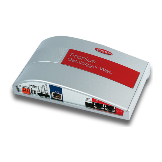
Page 8: Controls, Connections And Indicators
(1) Solar Web connection LED lights up green: when there is an existing connection to ‘Fronius Solar.web’ lights up red: when there is no connection to ‘Fronius Solar.web’ but one is required does not light up: when no connection to ‘Fronius Solar.web’ is required (2) Supply LED lights up green: when there is sufficient power coming from ‘Fronius Solar Net’... - Page 9 Ethernet interface colored in blue for connecting an Ethernet cable (9) External power supply connection for connecting an external power source when the power within ‘Fronius Solar Net’ is insufficient (e.g. when too many DATCOM components are installed in ‘Fronius Solar Net’).
-
Page 10: Installing 'Fronius Datalogger Web
= terminating plug = Fronius Com Card ‘Fronius Datalogger Web’ networks with several inverters, a ‘Fronius Sensor Box’ and a PC NOTE When networking several DatCom components, a terminating plug must be placed on each free IN and/or OUT connection of a DatCom component. -
Page 11: Preparations
Before Installing Important Please see the operating instructions for the inverter as well as the ‘Fronius IG DATCOM Details’ section. Install ‘Fronius Datalogger Web’ in the proper position using the screws and assembly dowels provided in the scope of delivery... -
Page 12: Fronius Datalogger Web' Network Configuration
DSL router can be used as a gateway address, for example. Important ‘Fronius Datalogger Web’ may not have the same IP address as the PC / laptop. ‘Fronius Datalogger Web’ cannot connect by itself to the Internet. A router must be used for a DSL connection to the Internet. - Page 13 (e.g. Microsoft Internet Explorer) Enter ‘http://169.254.0.180’ in the address field Set the IP address to ‘169.254.0.180’ The ‘Fronius Datalogger Web’ website will appear. Click on the ‘Settings’ menu item Website of ‘Fronius Datalogger Web’ Click on ‘Network’ Selection options in the ‘Settings’ menu item...
- Page 14 Select either a static or dynamic IP address (1) Obtain IP address static (factory setting): The user enters a fixed (static) IP address for the ‘Fronius Datalogger Web’ and also manually sets the subnet mask, gateway address and the DNS server address (from provider).
-
Page 15: Network Settings For Pc / Laptop
Network Settings for PC / Laptop General The PC / laptop is also a member of the network and must also be assigned a unique network address like the Datalogger. If the PC is already integrated in the network, no further settings are required. Network Settings Start / Control Panel / Network and for PC / Laptop... - Page 16 The subnet mask must correspond to the existing network (e.g. 255.255.255.0). The ‘Default gateway’ setting is not relevant for the ‘Fronius Datalogger Web’ connection. Important The PC / laptop may not have the same IP address as the ‘Fronius Datalogger Web.’ Activate ‘Obtain DNS server address automatically’...
-
Page 17: Internet Options For Pc / Laptop
Internet Options Open the Internet browser (e.g. for PC / Laptop Microsoft Internet Explorer) Click on ‘Tools’ Click on ‘Internet Options’ Click on the ‘Connections’ tab Click on the ‘LAN settings’ button at the bottom When the ‘Use a proxy server for your LAN’... - Page 18 Internet Options Enter the IP address of the for PC / Laptop ‘Fronius Datalogger Web’ in the (continued) ‘Exceptions’ field, e.g. 192.168.1.180 Click on the ‘OK’ button...
-
Page 19: Connecting To 'Fronius Datalogger Web' Via Lan And Internet Browser
Connecting to ‘Fronius Datalogger Web’ via LAN and Internet Browser General The connection to the ‘Fronius Datalogger Web’ via a LAN and Internet browser is suitable for accessing simple information by several PC users in a LAN (e.g. company networks, schools, etc.). -
Page 20: Connecting To 'Fronius Datalogger Web' Via Lan And 'Fronius Solar.access
Connecting to ‘Fronius Datalogger Web’ via LAN and ‘Fronius Solar.access’ General The connection to the ‘Fronius Datalogger Web’ via a LAN and ‘Fronius Solar.access’ is suitable for detailed long-term data entry and offers full settings options and data prepa- ration for the photovoltaic system. -
Page 21: For The Network Administrator
For the Network To access the Datalogger outside of the LAN: Administrator Configure the network router so that requests are forwarded to port 80 and port 15015 on the Datalogger... -
Page 22: Connecting To 'Fronius Datalogger Web' Via The Internet And 'Fronius Solar.web
The Datalogger is connected to the Internet (e.g. via a DSL router). The Datalogger logs view on to ‘Fronius Solar.web’ on a regular basis and sends its saved data every day. ‘Fronius Solar.web’ can establish an active contact with ‘Fronius Datalogger Web’ e.g. to display current data. -
Page 23: Accessing Data From 'Fronius Datalogger Web' Via The Internet And 'Fronius Solar.web
Accessing Data To access current and archived data from ‘Fronius Datalogger Web’ using ‘Fronius from ‘Fronius Solar.web’: Datalogger Web’ Open the ‘Solar Electronics’ heading on the Fronius website ‘www.fronius.com’ via the Internet Start ‘Fronius Solar.web’ and ‘Fronius Solar.web’ For more information about ‘Fronius Solar.web’ see the online help. -
Page 24: General Information For The Network Administrator
However, an Internet connection is required to use ‘Fronius Solar.web’ and send service Solar.web’ and messages. Sending Service Messages ‘Fronius Datalogger Web’ cannot connect by itself to the Internet. A router must be used for a DSL connection to the Internet. -
Page 25: Fronius Datalogger Web' Views
‘Fronius Datalogger Web’ Views Overview The following views are displayed on the ‘Fronius Datalogger Web’ website: Current total view Current comparison view Current Total The Current total view contains: View PV system power data savings per day and total Earnings per day and total... - Page 26 Current Compari- son View (continued) Current comparison view for 42 inverters (no. 1 and no. 49-89), inverter no. 1 is providing too little power Current comparison view for 3 inverters (no. 49, 50 and 51)
-
Page 27: Fronius Datalogger Web' Settings
‘Fronius Datalogger Web’ Settings Overview The following selection options are available in the ‘Settings’ menu of the ‘Fronius Datalogger Web’ website: Passwords Solar Web Date / Time Service Messages Views System Information Logging Firmware Update Network The Date/Time setting is mandatory The individual selection options will be explained in the following. -
Page 28: Passwords
Passwords ‘Password’ selection options User Password An assigned user password only gives the user read access to ‘Fronius Datalogger Web.’ The user cannot open the ‘Settings’ menu. Users must enter their username and password every time they connect to ‘Fronius Datalogger Web.’... -
Page 29: Administrator Password
An assigned administrator password gives the user both read and write access to Password ‘Fronius Datalogger Web.’ The user can then open the ‘Settings’ menu and make any changes as desired. When assigning an administrator password, the user must enter username and pass- word in ‘Fronius Datalogger Web’... -
Page 30: Date/Time
The time and date are saved for every data record that is logged. NOTE You must set the time and date in order to operate ‘Fronius Datalogger Web.’ This is the only way in which Datalogger data can be recorded. - Page 31 Date/Time (1) Datalogger time display (continued) (2) Datalogger date display (3) Datalogger time zone (4) Date/Time setting option: synchronize to PC / laptop or manual (5) Automatically adjust for daylight saving changes Important For the automatic daylight saving time setting, the correct time zone must be selected.
-
Page 32: Views
Views General Configuration of the ‘Fronius Datalogger Web’ website takes place in the views. The language, earnings and data for the comparison view can be set here. Views ‘Views’ selection options Default Language The ‘Fronius Datalogger Web’ website will appear in the set language. -
Page 33: Logging
Fronius sensor card / Fronius sensor box: 24 hours = 1440 minutes Establish total of logging points Total of logging points = = (number of inverters x logging points per Tag) + (number of Fronius sensor cards / boxes x logging points per day) -
Page 34: Calculation Example
Memory sectors per day Calculation 2 inverters, logging duration = 14 hours (840 minutes) Example 1 Fronius sensor card, logging duration = 24 hours (1440 minutes) Save interval = 15 minutes Logging points per day: 840 min Inverter logging points =... -
Page 35: Network
Network General The ‘Network’ selection option is used to configure ‘Fronius Datalogger Web’ for integra- tion with an existing network. For more information about network configuration for ‘Fronius Datalogger Web,’ please see section ‘Fronius Datalogger Web Network Configuration.’ Network ‘Network’ selection option... -
Page 36: Solar.web
Solar.web General The ‘Solar Web’ selection option is used to make a direct connection to ‘Fronius Solar.web’ from ‘Fronius Datalogger Web.’ For more information about ‘Fronius Solar.web,’ please see the section ‘Connecting to Fronius Datalogger Web via the Internet and ‘Fronius Solar.web’ or the ‘Fronius Solar.web’... -
Page 37: Service Messages
Service Messages General Service messages as well as errors from inverters, the ‘Fronius String Control’ etc. are sent to the Datalogger and saved. The ‘Service messages’ selection option is used to define how services messages are communicated. Communication can take place via:... - Page 38 Service Mes- (7) Message to fax recipient sages Activate to send service messages to a fax number (continued) (8) Field to enter country code e.g.: +43 = country code for Austria (9) Field to enter the fax area code (10) Field to enter the fax number (11) Field for sending daily (12) Selection field for the time when a service message will be sent via fax (13) ‘Send test fax’...
-
Page 39: System Information
System Information General The following system information for ‘Fronius Datalogger Web’ can be viewed in the ‘System information’ selection option: Datalogger ID Circuit board version Software version IP address Subnet mask Gateway DNS server MAC address Uptime User agent System Informati-... -
Page 40: Firmware Update
Download the current firmware from the Fronius homepage Run the downloaded update file on the PC / laptop This will start a web server from which ‘Fronius Datalogger Web’ will download the required files. Use your Internet browser to open the ‘Fronius Datalogger Web’ website... -
Page 41: Technical Data
Technical Data Technical Data Memory Capacity 16 MB Supply voltage 12 V DC Power consumption typ. 1.43 W Protection class IP 20 Dimensions 190 x 114 x 53 mm 4.69 x 4.49 x 2.09 in. Relay output 42 V AC / 6 A 60 V DC / 400 mA, 40 V DC / 1 A, 30 V DC / 6A Maximum cable cross section for the relay output 1,5 mm²... - Page 42 Fronius USA LLC Solar Electronics Division 4600 Wels-Thalheim, Günter-Fronius-Straße 1, Austria 10421 Citation Drive, Suite 1100, Brighton, MI 48116 E-Mail: pv@fronius.com E-Mail: pv-us@fronius.com http://www.fronius.com http://www.fronius-usa.com Under http://www.fronius.com/addresses you will find all addresses of our sales branches and partner firms! ud_fr_se_so_00913 012007...
Need help?
Do you have a question about the Datalogger Web and is the answer not in the manual?
Questions and answers