Table of Contents
Advertisement
Quick Links
Airborne Innovations LLC
07/26/16
Initial version
02/24/17
Added serial configuration
07/17/17
Updated
comms, ethernet switch info
08/11/17
Added technical note on J5 serial
08/08/18
Updated serial port pinout diagram
Picoradio Manual
info@airborneinnovations.com
720-515-3720
8 August 2018
Revision History
safety
precautions, radio options, serial port info, added mechanical drawing, long range
Advertisement
Table of Contents

Summary of Contents for Airborne Innovations Picoradio
- Page 1 Picoradio Manual Airborne Innovations LLC info@airborneinnovations.com 720-515-3720 8 August 2018 Revision History 07/26/16 Initial version 02/24/17 Added serial configuration 07/17/17 Updated safety precautions, radio options, serial port info, added mechanical drawing, long range comms, ethernet switch info 08/11/17 Added technical note on J5 serial...
-
Page 2: Table Of Contents
3.9 Picoradio Cable/Antenna Kit..........................14 3.9.1 Picoradio_Picoraptor Ext Ethernet Cable....................14 3.9.2 Picoradio Input Power Cable(one end cut)....................15 3.9.3 Picoradio Ext. Aux Power Cable (one end cut)..................16 3.9.4 Antenna Cable, U.FL to RP-SMA-Female....................18 3.9.5 2.4 GHz. Dipole ¼ wave Antenna, Connector, RP-SMA Male *.............18... -
Page 3: Introduction
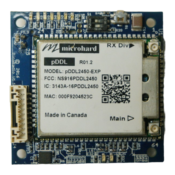
1 Introduction This document is a manual covering features and usage of the Airborne Innovations Picoradio OEM board. Warning: Make sure you read and follow the section 3.2, 'Safety Precautions' to avoid damaging the Picoradio. 2 Picoradio features The Picoradio is based around the Microhard pDDL radio, an advanced broadband COFDM datalink capable of high speed radio transmission and dual diversity receive. -
Page 4: Radio Options
Power In Serial Ethernet Power Figure 3: Picoradio Connectors 2.4.1 J1: Power Input Power input uses a wide input range efficient buck-boost converter (Typical efficiency ~94%). Input voltage range is 5-58V (note for full RF power radio operation the minimum voltage may be limited to about 7-8V). Short pins 1,2 and 3,4 together for full current capacity. -
Page 5: J2: Auxiliary Power Output
Airborne Innovations Picoradio Manual Pin# Description VCC In 5-58V VCC In 5-58V 2.4.2 J2: Auxiliary Power Output Auxiliary power out is available from this connector. The default output is 12V. Current available depends on the input voltage and RF output power setting of the radio (testing for your desired operating range is recommended). -
Page 6: J5: Serial Connector
Airborne Innovations Picoradio Manual Contacts: JST MINI-SSHL-002T-P0.2 Pin# Description ETH_1_T+ ETH_2_T- ETH_3_R+ POE_Vin+ ETH_6_R- POE_Vin- Link LED (disconnected by default- to connect a zero ohm resistor needs to be placed) The ethernet connections are also labeled with their typical pin number in an 10/100 RJ45 cable (1,2,3,6). -
Page 7: Technical Note On The Implementation Of J5 Serial
Airborne Innovations Picoradio Manual SW1: Enables RS232 mode SW2: Enables 3.3V TTL mode Figure 3: RS232/TTL switch (RS232 mode shown) 2.4.6 Technical note on the implementation of J5 Serial J5 uses a TXS0108ERGYR voltage translator / buffer with open drain capability, and a parallel MAX3243EEUI+ for switchable RS232 compatibility (with some added constraints due to this particular implementation). -
Page 8: Leds
Airborne Innovations Picoradio Manual 2.5 LEDs A number of status LEDs provide information on the radio status. RSSI1 RSSI3 3.3V RSSI2 The RSSI LEDs provide a bar graph indication of relative signal strength (and if illuminating in a repeating 1,2,3 sequence indicate the radio is searching for a signal). -
Page 9: Safety Precautions
Airborne Innovations Picoradio Manual Radios set to the same frequency • Frequency changed from the default at least once (likely due to a Microhard bug) • Encryption settings matching (Picoradios are typically supplied in an unencrypted version unless special •... -
Page 10: Long Range Operation
Airborne Innovations Picoradio Manual 3.4.3 Long Range operation Please note that the distance parameter on the RF configuration page should be set to a larger value than you are expecting to operate the radios at. It is also desirable for performance reasons not to set this to an excessively large number. -
Page 11: Logical Tcp Connection To One Remote Serial Port (Easiest Method To Test With Pixhawk Bidirectional Telemetry)
Airborne Innovations Picoradio Manual 3.5.3 Logical TCP connection to one remote serial port (easiest method to test with Pixhawk bidirectional telemetry) This could make sense for an application which connects to the serial port using a TCP style connection (such as MissionPlanner's TCP mode, or the telnet commandline tool). -
Page 12: Logical Point To Point Udp Connection To One Remote Serial Port
3.6 RF Amplifier Support The Picoradio may be used with a number of different RF amplifiers (regulatory issues apply and must be addressed by the user). AI can supply an 8W bidirectional RF amplifier which can be used, and which autodetects the TX/RX direction. -
Page 13: Mechanical Drawing
Airborne Innovations Picoradio Manual 3.8 Mechanical Drawing Figure 4: Picoradio mechanical drawing Page 13... -
Page 14: Picoradio Cable/Antenna Kit
Airborne Innovations Picoradio Manual 3.9 Picoradio Cable/Antenna Kit 3.9.1 Picoradio_Picoraptor Ext Ethernet Cable Page 14... -
Page 15: Picoradio Input Power Cable(One End Cut)
Airborne Innovations Picoradio Manual 3.9.2 Picoradio Input Power Cable(one end cut) Page 15... -
Page 16: Picoradio Ext. Aux Power Cable (One End Cut)
Airborne Innovations Picoradio Manual 3.9.3 Picoradio Ext. Aux Power Cable (one end cut) Page 16... - Page 17 Airborne Innovations Picoradio Manual PicoRadio Ext Serial Cable (one end cut) Page 17...
-
Page 18: Antenna Cable, U.fl To Rp-Sma-Female
Airborne Innovations Picoradio Manual PicoRaptor External Pixhawk Serial Cable 3.9.4 Antenna Cable, U.FL to RP-SMA-Female No Drawing Available 3.9.5 2.4 GHz. Dipole ¼ wave Antenna, Connector, RP-SMA Male * No Drawing Available *Antenna provided is for short range and bench testing.
Need help?
Do you have a question about the Picoradio and is the answer not in the manual?
Questions and answers