
Summary of Contents for Arca Flow Weka VLI EconomyLine 6
- Page 1 Installation and Operating Manual Visual Level Indicator (VLI) Date: 17.03.2020 Version: E 10.1...
- Page 2 Notes Order: Date: WEKA_IOM_VLI_EN / 17.03.2020 1 / 31...
-
Page 3: Table Of Contents
Content Type overview ................................3 Symbols and marks used ............................4 Safety information and warnings ..........................4 Intended use ................................5 The visual level indicator at a glance ........................6 The four different types of bypass ........................7 Top-of-tank design .............................. 7 Options Indication rail ............................ -
Page 4: Type Overview
Type overview 23614E EconomyLine 6 34000E EconomyLine 6 23614 StandardLine 6 34300 StandardLine 28 32755 StandardLine 50 34000 SmartLine 50 34110 SmartLine 50 36800 HighPressure Power 80 26411 HighPressure Power 100 25683 HighPressure Power 160 32806 HighPressure Power 200 26421 HighPressure Power 250 26431 HighPressure Power 315... -
Page 5: Symbols And Marks Used
Symbols and marks used Warning Indicates possible damage to the visual level indicator or injury to the operator or user if the instructions are not followed. Caution Indicates possible damage to the visual level indicator if the instructions are not followed. -
Page 6: Intended Use
Falling parts (screws, floats, etc.) may create impact sparks and lead to an explosion in potentially explosive atmospheres. Make sure that there isn’t a potentially explosive atmosphere and that no parts are falling when working on the visual level indicator. ... -
Page 7: The Visual Level Indicator At A Glance
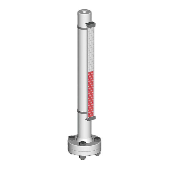
The visual level indicator at a glance Visual level indicators are used to continuously record the fluid level of the contents of a tank. They are connected as a bypass on the side of the tank, or as a top-of-tank gauge on the tank. Tank (container), supplied by customer Process connections*, supplied by customer... -
Page 8: The Four Different Types Of Bypass
The four different types of bypass Type A Type B Type K Type O Top process connection Lateral process connections, top and bottom Top service flange/plug Top service flange/plug Bottom service flange/plug Possible ventilation hole with plug Bottom process connection Bottom service flange/plug (Drain and vent omitted) Possible drain hole with plug... -
Page 9: Options Indication Rail
Options Indication rail See data sheets for more options. Measuring scale Reinforced Indication rail with Coloured gauge indication rail protective hose flaps mounting Function description The fluid level in the float chamber corresponds to the fluid level in the tank (communicating vessels). The bar magnet has been integrated into the float in a way that means the centre of the bar magnet is level with the surface of the liquid. -
Page 10: Scope Of Delivery For Visual Level Indicator
The magnetic field of the bar magnet penetrates the non-magnetic standpipe and rotates the gauge flaps by 180° when it goes past. Information on options: Magnetic switches and transducers can also be controlled using the bar magnet in the float. Magnets built into the gauge flaps keep the gauge flaps in position (magnetic coupling). -
Page 11: Remove Float Protection
Remove float protection If the float is not suitable for the intended use (density, max. operating pressure, max. operating temperature, connection dimensions, material, etc.), the visual level indicator may display an incorrect level, and it may be damaged and pose a risk. Make sure that the float is suitable for the intended application. - Page 12 A) Float attached 1. Detach the cardboard tube from the float chamber. 2. Open the cardboard tube and take out the float. 3. Remove the cardboard rings. 4. Remove the bottom service flanges/plugs. 5. Double check that the float is suitable for the chosen application using the highlighted data.
- Page 13 C) Float for top-of-tank designs 1. The float system for the top-of-tank design consists of a floatation body (called a float here), the magnet holder and the rod that connects the two parts. 2. Type 23013: The float moves along a guiding pipe and is fixed for transportation by a cable tie against movement.
-
Page 14: Installation
Installation Preparations for installing (point 8) the visual level indicator must be completed before installation. If the data marked on the type plate (density, max. operating pressure, max. operating temperature, connection dimensions, material, etc.), does not match the application, the visual level indicator may display an incorrect level, and it may be damaged and pose a risk to people and the environment. -
Page 15: Mounting
Mounting 1. Lay out the tools, lifting aids, screws, nuts and seals that you need to install the visual level indicator. 2. Position the visual level indicator on the tank. When doing so, make sure that the TOP sticker on the indication rail is pointing upwards. 3. -
Page 16: Maintenance
The visual level indicator is filled with liquid from the tank. When filling the tank for the first time, bear in mind that there will not yet be any liquid in the float outlet, and that the float will only float when this dead space has been filled via the lower socket. -
Page 17: Cleaning Visual Level Indicator
Cleaning visual level indicator 12.1 Cleaning the outside Polycarbonate indication rails may become statically charged – e.g. during cleaning. Sparks created when discharging in a potentially explosive atmosphere may cause an explosion. Only clean these parts with antistatic cleaning agents and tools. Caution Solvents and scouring agents may cause the indication rail window to become dull or cracked. -
Page 18: Cleaning The Float Chamber And Float For A Top-Of-Tank Assembly
3. Check the float. Floats with heavy signs of wear need to be replaced occasionally. When ordering replacements, make a note of the serial/order number and the item number to make clear assignment possible. If the density noted on the float doesn’t match with the density of the fluid, the visual level indicator will show an incorrect fill level. -
Page 19: Operating, Transport And Storage Conditions
4. Put the float system back in the float chamber and fit the float stopper, see chapter 8.3. 5. Reinstall the visual level indicator on the tank. Unsuitable screws, nuts and seals may result in leaks and cause damage and may endanger people and the environment. -
Page 20: Disposing Of The Visual Level Indicator
When opening the visual level indicator, bear in mind that the fluids and gases it contains could be hazardous to health. It is imperative that you comply with the safety data sheets for the process liquids and gases used. ... -
Page 21: Label
Gauge level different to surface of Incorrect float being used. Check whether the correct float the liquid (variation) has been used. - Deviation of several centimetres Float incorrectly in the standpipe. Check the orientation of the float and rotate it if necessary. Shift the magnet in the flat by Immersion depth of the magnet in tapping the float on a soft pad... -
Page 22: Eu Declaration Of Conformity For Non-Explosion-Proof Devices
EU Declaration of Conformity for non-explosion-proof devices WEKA_IOM_VLI_EN / 17.03.2020 21 / 31... -
Page 23: Eu Declaration Of Conformity For Explosion-Proof Devices
EU Declaration of Conformity for explosion-proof devices WEKA_IOM_VLI_EN / 17.03.2020 22 / 31... -
Page 24: Atex Certificate (Type Examination Certificate)
ATEX Certificate (Type Examination Certificate) WEKA_IOM_VLI_EN / 17.03.2020 23 / 31... - Page 25 WEKA_IOM_VLI_EN / 17.03.2020 24 / 31...
- Page 26 WEKA_IOM_VLI_EN / 17.03.2020 25 / 31...
-
Page 27: Iecex Certificate Of Conformity (Coc)
IECEx Certificate of Conformity (CoC) WEKA_IOM_VLI_EN / 17.03.2020 26 / 31... - Page 28 WEKA_IOM_VLI_EN / 17.03.2020 27 / 31...
- Page 29 WEKA_IOM_VLI_EN / 17.03.2020 28 / 31...
- Page 30 WEKA_IOM_VLI_EN / 17.03.2020 29 / 31...
- Page 31 WEKA_IOM_VLI_EN / 17.03.2020 30 / 31...
Need help?
Do you have a question about the Weka VLI EconomyLine 6 and is the answer not in the manual?
Questions and answers