Advertisement
Quick Links
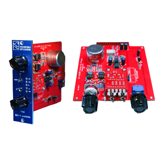
SC-1mk500 Mic Preamp Kit
Solid State, DC-Servo, Balanced Mic Preamplifier
with Input Transformer Option
Simplicity Counts, Detail Matters.
No part of this document may be reproduced, either mechanically or electronically, posted online on the Internet, in whole or in
part, without the expressed, written permission of FiveFish Studios. This document is solely provided
to the kit builder of the SC-1mk500 Mic Preamp Kit.
Copyright 2008 FiveFish Studios
www.fivefishstudios.com
Last Revision: November 29, 2008
Advertisement

Subscribe to Our Youtube Channel
Related Manuals for FiveFish Studios SC-1mk500 Mic Preamp Kit

Summary of Contents for FiveFish Studios SC-1mk500 Mic Preamp Kit
- Page 1 No part of this document may be reproduced, either mechanically or electronically, posted online on the Internet, in whole or in part, without the expressed, written permission of FiveFish Studios. This document is solely provided to the kit builder of the SC-1mk500 Mic Preamp Kit.
- Page 2 SC-1mk500 Mic Preamp Solid State, DC-Servo, Balanced Mic Preamplifier with Input Transformer Option Congratulations and thank you for your purchase of the SC-1mk500 Mic Preamp Kit. This is the 2 generation design of our popular SC-1 Mic Preamp Kit. Hundreds of hours have been spent in the design, manufacturing and packaging of this kit to deliver to you a great preamp, with the same features and performance found on some high-end boutique preamps.
- Page 3 Mini Long Nose Pliers – to bend component leads, use as a heatsink, hold components, tighten bolts. Manual Solder sucker pump or desoldering gun– sucks up solder when you made a mistake soldering components on the PCB. Pictured below is a Hakko model. Copyright 2008 FiveFish Studios www.fivefishstudios.com...
- Page 4 PanaVise – to hold PCB while you’re working on it Tweezers – to pick tiny things Masking tape – to hold components on the PCB while working Wire-stripper – for cutting wires and stripping its insulation Copyright 2008 FiveFish Studios www.fivefishstudios.com...
- Page 5 Yes, you read that right… EXPLODE. Do not the let the small size of an electrolytic capacitor fool you. Even a tiny electrolytic capacitor can explode with a lot of force. Copyright 2008 FiveFish Studios www.fivefishstudios.com...
- Page 6 The SC-1mk500 Preamp kit also uses inductors for RFI protection in the output stage. Inductors have no polarities, and just like resistors can be inserted in either orientation. The inductors we use look just like resistors. For your convenience, they are packed in a separate zip bag and labeled. Copyright 2008 FiveFish Studios www.fivefishstudios.com...
- Page 7 SC-1mk500 Microphone Preamp Kit Transistor We’re using a transistor as a switching device in the SC-1mk500 Mic Preamp Kit. The transistor has (3) legs, the Collector, Base and Emitter terminals. Looking from the top, the transistor has a half-circle shape, like a half-moon.
- Page 8 The green dot in the photo above marks the location of PIN 1 of the IC chip. There is also a notch on the IC body to show the proper orientation of the IC chips. Copyright 2008 FiveFish Studios www.fivefishstudios.com...
- Page 9 Some aluminum hex spacers, nut and bolts are included in the kit. Attach the VU Meters to the main preamp board using the aluminum spacers, and nut and bolts. Note how the VU meter is installed. The component side of the VU meter is facing upside down, and the copper portion is facing towards you. Copyright 2008 FiveFish Studios www.fivefishstudios.com...
- Page 10 Use a magnifying glass when soldering. This prevents you from using too much solder and let’s you see what you’re doing. Also, the Grayhill switch has very fine pin spacing. You need good eyesight to solder all pins properly without shorting them together. Copyright 2008 FiveFish Studios www.fivefishstudios.com...
- Page 11 IMPORTANT: Make sure you cut/snip the tab located on one side of the blue potentiometer. Cutting this tab will make the potentiometer stay straight and perpendicular to the Front Panel as you tighten the nut. Copyright 2008 FiveFish Studios www.fivefishstudios.com...
- Page 12 Avoid touching the metal pins of the IC chip. If you have a wrist ground strap, use it. Or better yet, use a grounded wrist strap. Failure to handle the chips properly without the proper anti-static precaution may damage the chips. Copyright 2008 FiveFish Studios www.fivefishstudios.com...
- Page 13 If you are USING an Input Transformer, solder the 6K8 resistor in the RLS location. STEP 14: Build the VU Meter Module. See the separate build instructions for the VU meter kit. Copyright 2008 FiveFish Studios www.fivefishstudios.com...
- Page 14 10. Make sure you cut/snip the tab located on one side of the blue potentiometer. Cutting this tab will make the potentiometer stay straight and perpendicular to the Front Panel as you tighten the nut. (Related to tip#7 above.) Copyright 2008 FiveFish Studios www.fivefishstudios.com...
-
Page 15: Audio Testing
If using a condenser mic, turn phantom power switch to ON position. Check to see if the LED lights up. Wait a few seconds, and your condenser microphone should start working. Check that your LED VU meters are working and blinking. Copyright 2008 FiveFish Studios www.fivefishstudios.com... - Page 16 Another method of reducing this type of noise is cryonic freezing. Wear a warm jacket. Problem: I want to record in stereo, but I only have (1) SC-1mk500 preamp. Buy another kit Copyright 2008 FiveFish Studios www.fivefishstudios.com...
- Page 17 Page 16 SC-1mk500 Microphone Preamp Kit SC-1mk500 PCB Component Layout Guide Copyright © 2008 FiveFish Studios Copyright 2008 FiveFish Studios www.fivefishstudios.com...
- Page 18 2K67 R10,R26 3K32 R2,R3, RLS R4, R5 R6,R7,R9 R8,R29,R30 100K 1K43 680R 324R 162R R15, R28 100R 63R4 40R2 or 39R2 25R5 15R8 10K POT, BOURNS LINEAR TAPER R24,R25 39R2 22K6 R31,R32 NOT USED Copyright 2008 FiveFish Studios www.fivefishstudios.com...
- Page 19 GREEN LED YELLOW LED RED LED NTE1866 0.1uf 100V C2,C3 0.47uf 50V 2K67 6K32 10K TRIMMER Spacer Aluminum 0.75" spacer Phillips pan head 4-40 x 1/4 4-40 x 1/4 Hex machine screw nuts 4-40 Copyright 2008 FiveFish Studios www.fivefishstudios.com...
Need help?
Do you have a question about the SC-1mk500 Mic Preamp Kit and is the answer not in the manual?
Questions and answers