
Summary of Contents for Oakley Sound Modular Series
- Page 1 Oakley Sound Systems 5U Oakley Modular Series The SVF issue 5 Voltage Controlled State Variable Filter Builder's Guide V5.3 Tony Allgood Oakley Sound Systems CARLISLE United Kingdom...
- Page 2 Introduction This is the Project Builder's Guide for the issue 5 State Variable Filter 5U module from Oakley Sound. This document contains a basic introduction to the board, a full parts list for the components needed to populate the board, interconnections and some basic testing methods. For the User Manual, which contains an overview of the operation of the unit, advice on connecting the unit and calibration procedures, please visit the main project webpage at: http://www.oakleysound.com/svf.htm...
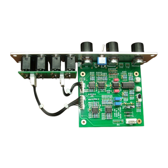
- Page 3 The SVF issue 5 PCB This is the prototype issue 5 module with natural finish Schaeffer panel. Note the use of the Sock8 board to mount the jack sockets. Two pot brackets are used to hold the PCB firmly to the front panel. I have provided space for the three main control pots on the PCB.
- Page 4 Components For general information regarding where to get parts and suggested part numbers please see our useful Parts Guide at the project webpage or http://www.oakleysound.com/parts.pdf. Some special considerations for this project The op-amps can be any decent medium (audio) speed op-amp, eg. TL072 or 4558. However, U2 should have a low input bias current and a FET input op-amp is to be recommended.
-
Page 5: Parts List
Parts List For general information regarding where to get parts and suggested part numbers please see our useful Parts Guide at the project webpage or http://www.oakleysound.com/parts.pdf. The components are grouped into values, the order of the component names is of no particular consequence. - Page 6 * C1 and C8 have a lead spacing of 5mm for the issue 5 SVF and a lead spacing of 2.5mm for issue 5.1. ** The PCB board locations for C2 and C7 were originally designed for 5mm 1% polypropylene capacitors and you can still use these if you wish. However, it is easier to get good quality C0G capacitors which work equally as well.
- Page 7 Cable tie for holding Q1 and Q2 together Molex or MTA 4 way header PSU – Oakley/MOTM power supply MTA100 6-way header PWR – Synthesizers.com power supply Molex/MTA 0.1” header 6-way UPPER – for connecting to sockets Molex/MTA 0.1” header 8-way LOWER –...
- Page 8 Mounting the Resonance Mode switch The switch is connected so that the when the toggle is in the up position the two connections of SAT are shorted together. You will need to connect your switch so that the lower two lugs of the switch are connected to the SAT pads on the board.
- Page 9 Connections Power connections – MOTM and Oakley The PSU power socket is 0.156” Molex/MTA 4-way header. Friction lock types are recommended. This system is compatible with MOTM systems. Power Pin number +15V Module GND Earth/PAN -15V Pin 1 on the LWR header has been provided to allow the ground tags of the jack sockets to be connected to the power supply ground without using the module’s 0V supply.
- Page 10 Building the 1U Filter Core module using the Sock8 board This is the simplest way of connecting all the sockets to the main board. The Sock8 board should be populated in the way described in our construction guide found on the project webpage.
- Page 11 Building the 1U Filter Core module by wiring the sockets manually If you have bought Switchcraft 112A sockets you will see that they have three connections. One is the earth or ground tag. One is the signal tag which will be connected to the tip of the jack plug when it is inserted.
- Page 12 2U SVF full format I am not going into great detail with this format as the PCB has been primarily designed with the 1U filter core module in mind. However, I will mention a few things that may be useful to you if you do decide to build the larger format design.
- Page 13 LOWER Pad name Socket Connection Lug Type Pin 1 Panel ground Connects to all sockets Ground lugs via wire frame Pin 2 LOWPASS Connect to LP Signal lug Pin 3 KEY-CV Connect to 1V/OCT Signal lug Pin 4 HIGHPASS Connect to HP Signal lug Pin 5 module ground See text...
- Page 14 Testing, testing, 1, 2, 3... Apply power to the unit making sure you are applying the power correctly. Check that no device is running hot. Any sign of smoke or strange smells turn off the power immediately and recheck the polarity of the power supply, and the direction of the ICs in their sockets. Assuming everything is OK so far, it is time to apply an audio input.
-
Page 15: Final Comments
Oakley modules. If you can't get your project to work and you are in the EU, then Oakley Sound Systems are able to offer a 'get you working' service. If you wish to take up this service please e-mail me, Tony Allgood, at my contact e-mail address found on the website.
Need help?
Do you have a question about the Modular Series and is the answer not in the manual?
Questions and answers