Table of Contents
Advertisement
Quick Links
Advertisement
Table of Contents

Subscribe to Our Youtube Channel
Related Manuals for Alton SUMMERHOUSE MICKLETON


Summary of Contents for Alton SUMMERHOUSE MICKLETON
-
Page 2: Table Of Contents
8’ x 9’ Cedar Summerhouse Assembly Instructions Contents: Section Page Introduction Base Preparation Overview Floor Assembly Side Assembly 9-14 Door Installation 15-16 Roof Assembly 17-25 Side Cloaking Fixing to Floor Roof Felting 28-31 Fascias and Capping 32-36 Slatted Roof Installation (optional) 37-40 Top Cap and Finial Casement Stay Set-up... -
Page 3: Introduction
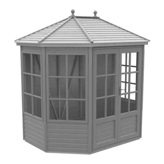
Introduction Thank you for purchasing your new Alton summerhouse. We recommend you familiarise yourself with the instructions and read all safety information before you commence assembly. This instruction manual is also available online at www.greenhousepeople.co.uk in the technical help section should you need to reprint it. Should you require any additional advice you can always call us on 01782 385409. -
Page 4: Base Preparation
Choose a site where the summerhouse is relatively easy to get to and convenient to bring a supply of electricity to. Finally, and most importantly, choose a site where your Alton summerhouse will look right so that it will complement your garden. -
Page 5: Overview
Overview To build your new summerhouse you will need the following tools: Spirit Level Pencil PZ2 Screwdriver Bit Cordless Screwdriver (2 would be ideal, 1 to drill and 1 to screw) 4mm Drill Bit Hammer Step ladders x 2 Hand Saw There are 8 different types of fixings used in the construction of the summerhouse. -
Page 6: Floor Assembly
Floor Assembly Begin by laying out two of the floor sections. The floor sections are handed, this is because of the notches in the sides so make sure you have one of each hand. Slide them together making sure the outside edges line up. - Page 7 Floor Assembly Now connect the two middle sections of flooring. Drill two pilot holes and fix together with 60mm passivated screws. Makes sure the groves in the floor boards line up before fixing. Diagram 4 Diagram 5 Next fix the rest of the base noggins to the middle section of flooring.
- Page 8 Floor Assembly Finally line up the other end section of flooring, before sliding this onto the noggins make a small mark on the floor board on the centerline of the noggin. This is to help you get the fixing screw in the correct position.
-
Page 9: Side Assembly
Side Assembly The positioning of the side panels is entirely flexible and can be decided as you fit them, so for example if you want an opening window in the rear corner of the building you can. This instruction manual will show the standard layout. - Page 10 Side Assembly Diagram 11 When fixing the panels bear in mind which faces will most visible when you walk into the building. Try to keep the screw heads on the least visible faces Diagram 12...
- Page 11 Side Assembly If you have followed the standard panel layout you can now fit a window section. Again it is up to you whether you chose a fixed window or opening window section. If the opening window is next to the door, the door does have the potential to knock into the window frame when open. If the cabin hook is used correctly this should not be an issue.
- Page 12 Side Assembly Fit the opposite panel as you did the last. Diagram 14...
- Page 13 Side Assembly Dia. 16 Diagram 15 Fitting the next panel requires slightly different approach as you can’t simply drill and screw through at right angles to the frame. You need to get the drill in as close as you can and drill at an angle through side of the frame.
- Page 14 Side Assembly Dia. 18 Fix this panel in the same way as Diagram 17 the last with the screws going though at a slight angle. Once you have done this should make 2 final fixings on the outside of the last two panels (diagram 18).
-
Page 15: Door Installation
Door Installation Diagram 19 Before you can install the door section you need to fit the door handle. Slide the Dia. 20 spindle through the lock to give you the position of the handle on the door. Fix the handle with the 3.5 x 25mm countersunk screws supplied. - Page 16 Door Installation Slot the door section into position, drill pilot holes shown by the arrows below (diagram 21) and fix with 60mm passivated screws. Again fix the panel at the top on the outside, making sure the screw head is flush with the surface (diagram 22). Dia.
- Page 17 Roof Installation You can now start to construct the roof. First you should fix the ridge infill (AB0024) to one of the ridge sections (AB0023). Drill two pilot holes in the infill section and fix with 40mm pan head screws. The infill should be level with the notches on the underside of the ridge section and extend beyond the ends by around 15mm (diagram 24).
-
Page 18: Roof Assembly
Roof Assembly Diagram 26 Next you can attach the two ridge brackets EV1004. Line the tab up with the grove on the underside of the ridge bar (diagram 26). Slot the two parts together, drill a pilot hole and fix with 50mm countersunk screws. - Page 19 Roof Assembly Diagram 28 Add the last bracket (EV1006) to the middle of the two ridge bars, drill pilot holes and fix this in place with four 50mm countersunk screws. Make sure this is central to the two ridge sections. Dia.
- Page 20 Roof Assembly With help lift the roof assembly onto the sides. Don’t fix this down until Diagram 31 all the roof bars are in place. Diagram 32 Now slot the rest of the roof bars into position. Fix them to the ridge brackets as you go.
- Page 21 Roof Assembly With all the roof bars in place you should then drill 2 pilot holes in the bottom of each roof bar. This should go vertically down so that the screw goes into the corner bar of the side frame. The diagram below shows a good position for the hole.
- Page 22 Roof Assembly With all the roof bars installed you can fit the soffit boards. Have a helper hold the soffit in position while you fix it from the inside through the pre-drilled holes with 4 x 80mm countersunk stainless steel screws. Its important to keep the ends inline with the joint between side panels. Diagram 34 These are fixed to the top of the side panels (diagram 35).
- Page 23 Roof Assembly AB0055 Diagram 36 Diagram 37 Work your around the building making sure ends of the soffits line up as closely as possible with the joint between side Dia. 38 panels. Diagram 38 AB0049...
- Page 24 Roof Assembly Its best to fit all the soffits to the sides leaving the last one in the least visible Diagram 39 place possible in case you have to trim the soffit or there is a slightly larger gap than normal. With all the roof bars fixed in place you can attach the ply roof sheets.
- Page 25 Roof Assembly Diagram 41 Make sure the ply roof sheet does protrude past soffits.
-
Page 26: Side Cloaking
Side Cloaking Diagram 42 AB0060 Work your way around the building fitting roof sheets, leaving double section single as you will use these as a template for the roof felt. Now is a good time to fit the side corner cloaking. Push the cloaking all the way up to the soffit and fix in place with AB0060... -
Page 27: Fixing To Floor
Fixing to Floor Diagram 45 Line the corner up with the floor before fixing You can now fix the sides to the floor. Drill pilot holes in the cill section of the side frame and fix down with 60mm screws. Diagram 46 2758mm... -
Page 28: Roof Felting
Roof Felting Take the role of roof felt (grit side down) and roll it out somewhere flat e.g. a garage floor. Also it is a good idea to have a sheet of ply or something similar to slide under the felt to protect the floor when cutting. Diagram 47 Lay the ply roof panel onto the felt as shown in diagram 48. - Page 29 Roof Felting Next you need to cut the top section of roof felt. Use diagram 50 below to mark out the first one. Once you have cut this out, as before use this as the template being careful not to damage it. Keep rotating this until you have 6 triangles ready to install.
- Page 30 Roof Felting Finally you need to cut two smaller pieces to go above the large felt sheets. Mark out the felt as shown below in diagram 43. Once you have cut these you can fix the ply roof sheets you have been using as templates.
- Page 31 Roof Felting Diagram 54 Work clockwise around the building until all the lower felt sheets are in place. Now fit the smaller felt sections above the larger ones. The bottom edge of the small sheet should be around 100mm below the top of the larger sheet to give a good overlap.
-
Page 32: Fascias And Capping
Fascias and Capping N.B. If you have the optional slatted roof go to section 11 now. Diagram 57 With all the felt in place you Dia. 58 can begin to fix the fascias. Start with the fascia above the door. You will notice the holes are slightly off-set, in this install they should be closest to the top of the fascia. - Page 33 Fascias and Capping When fitting the next fascia section adjust the position until you get a neat joint between the two sections. You may find you need to adjust the first one to get them to sit right. Measure from the underside of the soffit to get the fascia in the same position as the first.
- Page 34 Fascias and Capping Before you can fix the roof capping in place you need to trim it to length (the full length capping is used on the optional slatted roof). Trim the end with the bevel so the square end that goes at the bottom of the roof is kept tidy and pre-treated.
- Page 35 Fascias and Capping Diagram 62 Once all the corner capping pieces are in position space the tops out evenly and fix into position. Finish fixing the capping with the final 2 screws per strip. Diagram 63...
- Page 36 Fascias and Capping Finally fix the mid roof capping in place, you will also need to trim these to length (the full length capping is used on the optional slatted roof). Trim the end with the bevel so the square end that goes at the bottom of the roof is kept tidy and pre-treated.
-
Page 37: Slatted Roof Installation (Optional)
Slatted Roof Installation (optional) With all the felt in place you can lower the first slatted roof panel into place. Its best to start above the door and work around the building from there. Ask a helper to hold the first roof panel while you position the fascia board below. - Page 38 Slatted Roof Installation (optional) When fitting the next fascia board adjust the position until you get a neat joint between the two boards. You may find you need to adjust the first one to get them to sit correctly. You will need to trim the felt at the corners, trim the bottom layer and overlap the top layer.
- Page 39 Slatted Roof Installation (optional) Diagram 71 When all of the fascias are in place lay on the rest of the roof panels. Now you can fit the capping working your way around the building. As you position each one, line the end up with the outer point of the joint between fascias (diagram 71).
- Page 40 Slatted Roof Installation (optional) Once all the capping pieces are in position space the tops out evenly and fix into position. Diagram 72 Finish fixing the capping with the final 3 screws per strip. Diagram 73...
-
Page 41: Top Cap And Finial
Top Cap and Finial First mark the centre point between the long edges, then measure the same distance in from each end and make another mark. Drill two pilot holes. Then find the centre point of the finial (AB0106) and mark this. Fix the two parts together with a 50mm countersunk stainless steel screw. -
Page 42: Casement Stay Setup
Casement Stay Setup Remove the casement stay peg Diagram 77 from below the window rail, keep the screw as you will need this to re-attach the peg (diagram 77). Then remove the transit screw and washer from the casement stay handle, again keep this screw for the peg (diagram 78). -
Page 43: Cabin Hook Fitting
Cabin Hook Fitting Firstly fit the cabin hook eye plate to the door. This should fit close to the bottom of the mid rail and 333mm in from the hinge side (diagram 80). Fix in place with two 25mm countersunk stainless steel screws. - Page 44 Cabin Hook Fitting With the cabin hook (AB0145) slotted onto the eye, position the back plate of the hook against the side panel. This should be fixed just below the window frame to make sure it doesn’t interfere. Screw the first 25mm screw into the top hole of the back plate, and the second screw in the bottom hole should be angled up slightly to be sure to pick up the softwood frame behind.
-
Page 45: Architrave Fitting
Architrave fitting Diagram 84 Dia. 85 Finally you need to fit the architrave on the inside of the door frame. Measure 12mm from the inside face of the door frame (diagram 85) and make a mark at the top and bottom AB0093 on each side. -
Page 46: Window Trim Fitting
Window trim fitting Dia. 87 Diagram 86 As with the architrave the window trims are fitted with four panel pins per side. (diagram 86). These need to be fitted to all window sections. Diagram 87... - Page 47 Weather Strip Fitting Diagram 88 Finally you need to attach the weather strips to all the panels with windows fitted. These locate with the cladding as shown in diagram 89. Push it tight up against the cladding above. You then simply screw from the inside of the building through the cladding as close to the horizontal rail as...
- Page 48 Notes...
- Page 49 Notes...
- Page 50 Notes...
- Page 51 BOM No. Part No. Part description Quantity ABCEDOCT89 Octagonal Summerhouse 8x9 Box ABA0015 Oct Base Assembly 88 LH 2 ABA0016 Oct Base Assembly 88 RH 2 ABA0018 Oct Base Insert Assembly 89 2 ABA0027 SH Oct Side Panel Clad_Double_Plain 1 ABA0037 SH Oct Side Panel Clad_Single_88_89_Plain 2 ABA0038F SH Oct Side Panel Clad_Single_88_89_Window_Fixed 2 ABA0038V SH Oct Side Panel Clad_Single_88_89_Window_Vent 2 ABA0041 ...
- Page 52 Alton Garden Buildings, TGP Ltd, Blythe Park, Cresswell, Stoke-on-Trent, ST11 9RD Telephone: 01782 385 409 www.Altongreenhouses.co.uk sales@altongreenhouses.co.uk...
Need help?
Do you have a question about the SUMMERHOUSE MICKLETON and is the answer not in the manual?
Questions and answers