
Subscribe to Our Youtube Channel
Summary of Contents for Alfa Network Color Lab
- Page 1 Operator Manual Color Lab ORIGINAL INSTRUCTION Code: Year: 2019 Rev.: www.alfadispenser.com...
- Page 2 Operator Manual – Color Lab Page left intentionally blank ITALIANO...
- Page 3 Operator Manual – Color Lab Alfa Srl Via Caduti di Ustica, 28 - Calderara di Reno 40012 BOLOGNA – Italy Tel +39 051 0828494 Fax +39 051 0823283 © Copyright 2015 Tutti i diritti riservati © Copyright 2015 All rights reserved Total or partial reproduction, modification and translation of the present manual is forbidden without previous authorisation of Alfa Srl.
- Page 4 Operator Manual – Color Lab Page left intentionally blank...
-
Page 5: Table Of Contents
GENERAL RECOMMENDATIONS ......................21 2.1.1. DIMENSIONS OF THE PACKAGE ....................21 2.2. UNPACKING ............................21 2.2.1. COLOR LAB COMPLETE WITH MASTER CABINET ..............22 2.2.2. COLOR LAB TABLETOP VERSION ....................22 2.3. OPENING PACKAGE AND CHECKING THE CONTENT ..............23 2.4. - Page 6 Operator Manual – Color Lab INSTALLATION..............................24 3.1. CHOOSING THE ROOM .........................24 3.2. PRODUCT LABEL AND ELECTRICAL CONNECTION .................24 3.3. REMOVING THE MECHANICAL RETAINERS ..................25 3.3.1. DYE TANK RETAINER REMOVAL ....................25 3.3.2. MASTER TANK RETAINER REMOVAL ...................25 3.3.3. CONNECTING THE MASTER CIRCUITS ..................25 3.3.4.
-
Page 7: Foreword
0.1.1. IMPORTANCE OF THE MANUAL The manual contains instructions and advice for the commissioning and use of the Color Lab product. Before installing and commissioning the system, carefully read this manual in all its parts and in particular the chapters “GENERAL INFORMATION”, “INSTALLATION”... -
Page 8: Symbols Used In The Manual
Operator Manual – Color Lab 0.1.4. SYMBOLS USED IN THE MANUAL The safety and advice symbols used in this manual are used to draw the reader’s attention to warnings concerning safety or indicating good working practices. The same symbols are also placed on the machine to indicate dangerous areas and refer to the relevant safety notes in the manual. -
Page 9: Safety Information
86/188/EEC regulations. 0.3.2. GENERAL SAFETY WARNINGS Color Lab is compliant with all the safety requirements of the main European and extra-European Standards and Institutions. Despite that, it is suggested to read carefully the information contained in this chapter and in the next pages since they show the possible dangerous situations and the necessary precautions to take. -
Page 10: Users And Access Levels
MAINTENANCE AREA: the area inside the machine, which can be accesses with a key, where ordinary maintenance operations are usually performed (on Color Lab such operations are performed by the MAINTENANCE OPERATOR); extraordinary maintenance operations require the access to the SERVICE AREA and are performed by the TECHNICIAN (replacement of dispensing units, circuits, electric parts);... -
Page 11: General Information
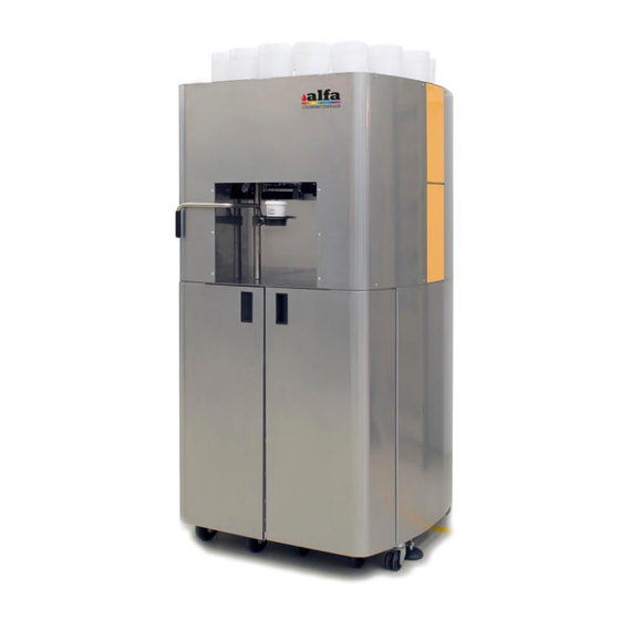
Operator Manual – Color Lab 1. GENERAL INFORMATION 1.1. INTRODUCTION The Color Lab is a laboratory machine that can be used to produce colour samples in volumes ranging from 100 ml to 1 L. The machine is equipped with 16 dispensing circuits for... -
Page 12: Description Of The Machine
Operator Manual – Color Lab 1.3. DESCRIPTION OF THE MACHINE The paragraph describes the main external and internal components of the machine and their function. 1.3.1. EXTERNAL COMPONENTS OVERVIEW OF MAIN ELEMENTS Dye units Electrical control panel Colour sample support arm... -
Page 13: Can Support Arm
Operator Manual – Color Lab 1.3.1.3. CAN SUPPORT ARM The machine produces colour samples in volumes ranging from 100cc to 1 litre. The support arm (1) can be positioned at different heights in order to accommodate cans of appropriate volumes, based on the quantity to be dispensed. -
Page 14: Autocap
Operator Manual – Color Lab 1.3.2.3. AUTOCAP This unit normally keeps the area under the dispensing nozzles moist and sealed to reduce any drying issues. An automatic moisturising system ensures a constant and optimal moisturising in the dispensing area sealed with a –... -
Page 15: Alarms
Operator Manual – Color Lab 1.4.3. ALARMS The interface installed on the machine, which can be viewed using a Web Browser (e.g. Google Chrome), shows in real time any critical machine alarms requiring immediate operator intervention and preventing the use of the machine, as well as non-critical alarms, reminding the operator of (even not immediately) required service operation(s). -
Page 16: Working Cycle
Operator Manual – Color Lab 1.4.6. WORKING CYCLE User selects the colour and presses production start, then the machine checks that the vessel is present under the dispensing nozzle, and then runs the following work stages: AUTOCAP OPENING PAINT DISPENSING AUTOCAP CLOSING RETURN TO STANDBY. -
Page 17: Dimensions And Weight
Operator Manual – Color Lab 1.5.4. DIMENSIONS AND WEIGHT Height 750 mm Height with cabinet 1540 mm Width 800 mm Depth 800 mm Weight with cabinet (empty) 190 Kg excluding masters Weight with cabinet (fully approximately 220 Kg loaded) excluding masters Master tray weight (empty) 1.5.5. -
Page 18: Residual Risks And Dangerous Areas
Operator Manual – Color Lab 1.6. RESIDUAL RISKS AND DANGEROUS AREAS USER AND MAINTENANCE OPERATOR The potentially dangerous areas associated with mechanical moving parts are described below: − autocap system: risk of entrapment for the hands, fingers, hair and/or clothing due to autocap opening/closing movement. -
Page 19: Certifications
Illegal disposal of the product by the owner causes the imposition of administrative sanctions as indicated by the law in force. For safe machine packaging and handling it is recommended to use a pallet for Color Lab, equipped with the necessary fixing points (see para. 2). -
Page 20: Ec Declarations
Operator Manual – Color Lab 1.7.4. EC DECLARATIONS The equipment complies with the following European Directives: 2006/42/EC, 2014/35/EU, 2014/30/EU, 2011/65/EU. GENERAL INFORMATION... -
Page 21: Unpacking
Operator Manual – Color Lab 2. UNPACKING 2.1. GENERAL RECOMMENDATIONS The machine is delivered on a wooden pallet covered with corner protectors and triple wall cardboard in order to avoid any risk of damage during transport. All the accessories supplied are contained in the same wooden case. -
Page 22: Color Lab Complete With Master Cabinet
Operator Manual – Color Lab 2.2.1. COLOR LAB COMPLETE WITH MASTER CABINET • Follow the instructions below • Open the doors of the cabinet and extract the tank support trays (if present), which initially come disconnected. • After loosening the nuts present on the internal surface... -
Page 23: Opening Package And Checking The Content
Autocap sponge kit. 2.4. MOVING THE MACHINE Color Lab must only be moved under conditions of maximum safety. In order to move the machine with the cabinet, it is possible to raise the support feet and use the dedicated wheels. -
Page 24: Installation
Operator Manual – Color Lab 3. INSTALLATION 3.1. CHOOSING THE ROOM The machine must be installed in a manned room, complying with the requirements in chapter 1. DO NOT INSTALL THE MACHINE OUTDOORS OR ANYWHERE EXPOSED TO WEATHER. THE EQUIPMENT IS NOT SUITABLE FOR INSTALLATION IN AREAS WHERE WATER SPRAY COULD BE USED. -
Page 25: Removing The Mechanical Retainers
Operator Manual – Color Lab 3.3. REMOVING THE MECHANICAL RETAINERS Some mechanical retainers prevent movement of machine components to avoid damage during transport. After unpacking and before commissioning, remove all mechanical retainers as follows: 3.3.1. DYE TANK RETAINER REMOVAL Tanks are fastened to the lower pull-out tank by means of screwed knobs. -
Page 26: Control Pc Installation
Operator Manual – Color Lab Finally, connect the electrical component using the dedicated connector. After having completed the above operations, reposition the trays inside the cabinet and lock them in place by engaging the wheel brakes. Close the doors when finished. -
Page 27: Control Software
Operator Manual – Color Lab 3.3.5. CONTROL SOFTWARE To control the dispenser, Alfa makes the web-based interface called AlfaTint available to all its customers. In case you wish to apply your own software, Alfa provides a series of calls (API Rest) allowing interfacing the machine with any third-party software. - Page 28 Operator Manual – Color Lab Check that the accessory kit includes: • Modem • Network cable • No. 2 antennae If necessary the antenna equipped with cable and magnet can be used. INSTALLATION...
-
Page 29: Switch-On And Initialisation
Operator Manual – Color Lab 3.4. SWITCH-ON AND INITIALISATION Connect a PC to the machine Ethernet “0.100” socket using the supplied Ethernet cable, then proceed as described. • MACHINE: Update the PC network configuration so that the IP address is within the same subnet as that of the machine (see the adjacent example). -
Page 30: Commissioning - Preparation
Operator Manual – Color Lab 3.6. COMMISSIONING - PREPARATION 3.6.1. DYE CANISTER LOADING Each colorant group is matched to a hardware address. By convention, colorant order is as shown in figure below. The canisters are always marked with labels from C1 to Cn, according to the actual number of present circuits. -
Page 31: Semi-Finished Product Loading
Operator Manual – Color Lab 3.6.2. SEMI-FINISHED PRODUCT LOADING The semi-finished products must be loaded into the 22-litre stainless steel tanks present in the lower part of the machine. • Fill as follows: • Open the machine front doors and extract the master trays (after disengaging the wheel brakes). -
Page 32: Semi-Finished Product Circuit Opening
Operator Manual – Color Lab 3.6.4. SEMI-FINISHED PRODUCT CIRCUIT OPENING Under the tanks there are the relevant pumping units provided with shut-off valves (1). Upon commissioning and before testing the circuits, check that the valves are open. 3.6.5. SWITCH-ON AND INSPECTION... -
Page 33: Setup Of Circuits
Operator Manual – Color Lab 3.6.7. SETUP OF CIRCUITS The machine is now ready to be initialised or for producing the first sample. Typically, the machines leave the factory with all circuits already characterised and ready to be used with the colorants of the tinting system specified in the order. -
Page 34: How To Produce A Colour
Operator Manual – Color Lab 4. HOW TO PRODUCE A COLOUR 4.1. MACHINE STATUSES On top right of the Alfa TINT software interface you can always see the machine (1) status. Following are the possible machine statuses: STANDBY: machine ready, waiting for controls... -
Page 35: Creation Of A New Formula And Change Of An Existing One
Operator Manual – Color Lab 4.2.2. CREATION OF A NEW FORMULA AND CHANGE OF AN EXISTING ONE If a formula is modified starting from a laboratory one or if a new formula is created from scratch, this formula is not saved among the laboratory ones but in dedicated and different space (e.g. -
Page 36: Service Advanced Functions
Operator Manual – Color Lab 4.4. SERVICE ADVANCED FUNCTIONS The “Service” tab allows accessing useful functions for the diagnosis maintenance operations. Inside this interface it is possible to send the following direct controls to the machine: • Purge • Warm Reset (without movements) •... -
Page 37: Ordinary Maintenance And Adjustments
Operator Manual – Color Lab 5. ORDINARY MAINTENANCE AND ADJUSTMENTS 5.1. INTRODUCTION The following paragraphs describe the circuit top-up operations as well as the instructions for simple adjustments that can be performed by the operator. Namely: • Colorant and master tanks top-up •... -
Page 38: Recording The Operation
Operator Manual – Color Lab 5.3. RECORDING THE OPERATION After each top-up operation it is necessary to record in the software the product added quantity: • Access the “Service” section and then “Diagnostic Mode”; • In the “Add [cc]” field enter the volume in cc of the product supplied in the circuit, then press “+”. -
Page 39: Adjusting Minimum Levels
Operator Manual – Color Lab 5.5. ADJUSTING MINIMUM LEVELS 5.5.1. ADJUSTING COLORANT RESERVE Colorant tanks feature a gravimetric level detection system. A spring is compressed by the force exerted by the weight of the canister above, thus causing a microswitch to close and signal the presence of colorant inside the tank. -
Page 40: Product Disposal
Operator Manual – Color Lab 5.6. PRODUCT DISPOSAL During the maintenance or repair interventions it may be necessary to empty canisters and tanks from the paints contained in the circuits. Colorants and base must be disposed of in suitable collector tanks to be treated and disposed of in a suitable way. -
Page 41: Lubrication And Cleaning
Operator Manual – Color Lab 6. LUBRICATION AND CLEANING 6.1. SCHEDULED MAINTENANCE The following table indicates the scheduled maintenance recommended by Alfa. SERVICE OPERATION INTERVAL Lubrication none Autocap cleaning and moisturising weekly Nozzle cleaning + Purge daily Machine external cleaning... -
Page 42: Service Equipment
Operator Manual – Color Lab 6.2. SERVICE EQUIPMENT Below is a list of the required equipment for the service operations. Blotting paper, clean cloth/sponge Plastic spatula Thin metal wire or clip (to clean colorant nozzles) Thin tip tool or 2.5 mm flat screwdriver (for... -
Page 43: Autocap Cleaning And Moisturising
Operator Manual – Color Lab 6.4. AUTOCAP CLEANING AND MOISTURISING Humidifier level refilling (if any) Regularly check, through the inspection window (1), the level of liquid present in the tank (2). If the level is low, refill by loosening the red cap (3) and adding distilled water. -
Page 44: Purge
Operator Manual – Color Lab 6.6. PURGE This function consists in dispensing a small quantity of product from one or several circuits, so as to ensure proper cleaning of the dispensing circuits and prevent settling or drying out issues that could compromise machine operation. -
Page 45: Collector Tanks Beneath The Masters
Operator Manual – Color Lab 6.8.2. COLLECTOR TANKS BENEATH THE MASTERS Collector tanks or sheets may be added under the pull-out tray of the base tanks. If required, change tanks or sheets with clean elements and throw away or clean up the removed elements, taking suitable precautions to dispose of the waste. -
Page 46: Replacing The Fuses
Operator Manual – Color Lab 6.9. REPLACING THE FUSES In case of mains malfunction or problems, the safety fuses could blow and cut power. Fuses are located in the fuse holder built in the plug with switch on the back panel (see chapter 1 - ELECTRICAL CONTROL PANEL) To change it, remove power plug and open fuse holder using a flat screwdriver to prise it open. -
Page 47: Extraordinary Maintenance
Operator Manual – Color Lab 7. EXTRAORDINARY MAINTENANCE The extraordinary maintenance operations require access to the service areas and area reserved for specialised technicians. ALWAYS ENTRUST THE SPECIAL MAINTENANCE INTERVENTIONS TO AN AUTHORISED SUPPORT CENTRE. THE MACHINE POWER CABLE MUST BE UNPLUGGED FROM THE MAINS BEFORE ACCESSING THE SERVICE AREA AND BEFORE PERFORMING ANY REPLACEMENT/REPAIR OPERATIONS. -
Page 48: Trouble Shooting
Operator Manual – Color Lab 8. TROUBLE SHOOTING ERROR ERROR ERROR PROBLEM CODES DETECTED DESCRIPTION RESOLUTION Timer operation test Test failure means that the program on the MAB TIMERMG_TEST_FAILED failure board has stopped working. Restart the program Check for the absence of parameters in the case... - Page 49 Operator Manual – Color Lab ERROR ERROR ERROR PROBLEM CODES DETECTED DESCRIPTION RESOLUTION Verify the cleanliness and positioning of the photocell mounted on the ”X” BASE, then clean or reattach the sensor. Verify the integrity of the "X" BASE slave reset “flag”, the pusher, the motor, and the connectors,...
- Page 50 Operator Manual – Color Lab ERROR ERROR ERROR PROBLEM CODES DETECTED DESCRIPTION RESOLUTION At the end of the movement from HOME B”X”_COLOR_POS0_READ_LIGHT_ER 601-608 position to POS0 the Check photocell and stepper operation ROR, where “X” = 1..8 photocell is NOT engaged in the "X"...
- Page 51 Alfa Srl Timbro rivenditore Sales Mark Headquarters: Via Caduti di Ustica, 28 I-40012 – Calderara di Reno (BO), Italy Tel. +39 (0)51 0828494 Fax +39 (0)51 0823283 Registered Office: Via Farini, 4 I- 40124 – Bologna, Italy VAT: IT-03364471205 – REA BO: 513367 Shared Capital €...
Need help?
Do you have a question about the Color Lab and is the answer not in the manual?
Questions and answers