Table of Contents
Advertisement
Quick Links
Build Guide
Build Guide:
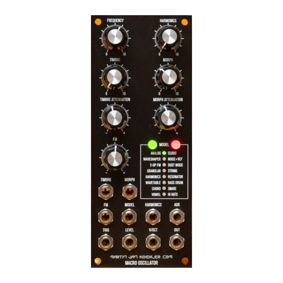
Macro Oscillator for 5U modular synthesizer
Format: MOTM
Version: v2a
Macro Oscillator in 5U (MOTM)
Introduction
This module is an 5U adaption based on the
famous Eurorack module "Plaits" invented by Émilie
Gillet, the successor to the popular "Braids"
module:
https://www.martinjankoehler.com/synthesizers/
synth-macro-oscillator-in-5u/
This document describes the assembly of the
ported module.
License information
•
PCB, Panel & Build Guide:
CC-by-SA-3.0 Martin Köhler
•
Schematics & Firmware:
CC-by-SA-3.0 Émilie Gillet
https://mutable-instruments.net/modules/plaits/
open_source/
Page
1
of
18
Advertisement
Table of Contents

Subscribe to Our Youtube Channel
Summary of Contents for MJK Macro Oscillator
-
Page 1: Introduction
Build Guide Macro Oscillator in 5U (MOTM) Page Build Guide: Macro Oscillator for 5U modular synthesizer Format: MOTM Version: v2a Introduction This module is an 5U adaption based on the famous Eurorack module "Plaits" invented by Émilie Gillet, the successor to the popular "Braids"... -
Page 2: Table Of Contents
Build Guide Macro Oscillator in 5U (MOTM) Page Table of Contents Introduction License information Table of Contents Bill of Materials (1 / 2) Bill of Materials (2 / 2) PCB overview and recommendations Soldering the Main Board 1. Part A – Water Washable Flux 1.1.SMT parts (back side) -
Page 3: Bill Of Materials (1 / 2)
Build Guide Macro Oscillator in 5U (MOTM) Page Bill of Materials (1 / 2) Macro Oscillator / 5U edition CC-by-SA-3.0 Martin Jan Köhler Format: MOTM PCB v2 BOM v2b CC-by-SA-3.0 Émilie Gillet by martinjankoehler.com Index Description Specs Value Package... -
Page 4: Bill Of Materials (2 / 2)
Build Guide Macro Oscillator in 5U (MOTM) Page Bill of Materials (2 / 2) Macro Oscillator / 5U edition CC-by-SA-3.0 Martin Jan Köhler Format: MOTM PCB v2 BOM v2b by martinjankoehler.com CC-by-SA-3.0 Émilie Gillet Index Description Specs Package References... -
Page 5: Pcb Overview And Recommendations
Build Guide Macro Oscillator in 5U (MOTM) Page PCB overview and recommendations The PCB contains 3 parts that will be interconnected using MTA-100: 1. main board 2. push button and LED board 3. jack board I recommend not to break out the three parts of the PCB at this point, that’s nicer to solder IMHO. -
Page 6: Soldering The Main Board
Build Guide Macro Oscillator in 5U (MOTM) Page Soldering the Main Board 1. Part A – Water Washable Flux Start with the back side (opposed to the front side which is oriented towards front panel). 1.1. SMT parts (back side) Start with soldering the SMT ICs U2 and U5. - Page 7 Build Guide Macro Oscillator in 5U (MOTM) Page...
-
Page 8: Front Side
Build Guide Macro Oscillator in 5U (MOTM) Page 1.3. Front side We’ll leave the front side as-is until later when the user interface elements (potentiometers, LEDs, push buttons) will be fitted. 1.4. Back side Populate the PCB according to the large photograph on the next page. -
Page 9: Separate Pcb Parts
Build Guide Macro Oscillator in 5U (MOTM) Page Separate PCB parts Use a fine side cutter to separate PCB into the 3 parts / boards by cutting the little bridges between the mouse bites. - Page 10 Build Guide Macro Oscillator in 5U (MOTM) Page...
-
Page 11: Prepare And Solder Cables
Build Guide Macro Oscillator in 5U (MOTM) Page Prepare and Solder Cables Type Qty Pins Length Mother Board Daughter Board Connection Connection Normalization AWG 22 multi 5 5P 6 cm Directly soldered MTA-100 strand drilled according to PIN 1 (KK or IDC) -
Page 12: Front Panel: Hex Nuts
Build Guide Macro Oscillator in 5U (MOTM) Page Front panel: hex nuts Fit the five hex nuts to the back side front panel to secure the button/LED board. Buttons Solder the push buttons to the LED/button PCB. -
Page 13: Leds And Screws
Page Build Guide Macro Oscillator in 5U (MOTM) LEDs and screws Fit the LEDs through the footprints on the front side of the PCB. VERIFY: Match the orientation according to the picture (shorted lead goes through the left-most hole). Put the front panel on top and turn over the sandwich. -
Page 14: Potentiometers
Page Build Guide Macro Oscillator in 5U (MOTM) Potentiometers Using the pliers, break off the little tabs of the potentiometers. For securing the potentiometer nuts, a tool is recommended that does not scratch the front panel. So do not use a regular wrench, but a hex key tool as in the picture. - Page 15 Build Guide Macro Oscillator in 5U (MOTM) Page...
-
Page 16: Jack Board
Start with the middle (FM, V/OCT), then work your way towards the edges. VERIFY: to conform to MJK’s OCD, make sure to align the hex nuts with one corner facing top ;-) The backside of the finished modules should look... - Page 17 Page Build Guide Macro Oscillator in 5U (MOTM)
-
Page 18: Tests And Calibration
Build Guide Macro Oscillator in 5U (MOTM) Page Tests and Calibration Set your lab power supply to +15V (current limit 70mA) and -15V (current limit 15mA) and turn it on and verify that the current limit is not reached (which could mean that there are shorts), and that no parts are getting hot or magic smoke escapes.
Need help?
Do you have a question about the Macro Oscillator and is the answer not in the manual?
Questions and answers