Table of Contents
Advertisement
Quick Links
Advertisement
Table of Contents

Summary of Contents for Metra Electronics Tripod
- Page 1 Tripod Turnstile Technical Manual...
-
Page 2: Table Of Contents
Tripod Turnstile Technical Manual Table of contents Tripod Turnstile Technical Manual ......................3 Product description ..........................3 Basic parts ............................4 Wristband Capturer (optional) ....................... 4 Antenna with Reader (optional) ..................... 4 On the outside ..........................5 On the inside ........................... 5 Mounting set (optional) ........................ -
Page 3: Tripod Turnstile Technical Manual
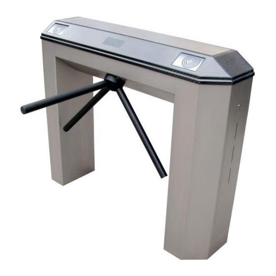
Metra inženiring would greatly appreciate being informed of them. Metra inženiring d.o.o. can assume no responsibility for any errors in this manual. Product description Tripod Turnstile is a complete, compact access control point. It combines motorized rotating barrier with RFID readers to control entrance and exit. Because everything is integrated into a single housing, it reduces required space for passage. -
Page 4: Basic Parts
Tripod Turnstile Technical Manual Tripod Turnstile is connected to Metra NET Network. When RFID Ticket is presented, access rights are checked in the Metra software check engines. If valid, the unit drives its rotating barrier in desired direction. Passage on Tripod Turnstile for a particular ticket can also be externally controlled by 3 party SW via TCP/IP software interface. -
Page 5: On The Outside
Wristband capacity control windows On the inside There are four main components inside the Tripod Turnstile. Those are: Master PCB, Slave PCB, Turnstile Drive Mechanism II (Mechanism and Motor Driver PCB) and Wristband Capturer (optional). Consult the “Turnstile Drive Mechanism II – Technical Manual” and “Wristband Capturer – Technical Manual”... -
Page 6: Mounting Set (Optional)
Choosing location for installation Placement of device is chosen regarding the project plan. Take into consideration the following advices regarding the orientation and location of Tripod Turnstile(s): Receptionist should have good overview to the front side of the device(s). - Page 7 Tripod Turnstile Technical Manual If there is more than one device in a row, only the first Turnstile needs a fixed barrier. Other devices are using next device as a barrier. On the left and right side of the device there need to be at least 30 cm of free space to take out the storage with captured tickets.
-
Page 8: Wires Installation
Metra Net Network), more than one ribbed plastic hose can be put in. Each installed cable should be at least 1.5 metre long from the ground. Wiring NOTE Cables are always installed through the leg on the ENTRANCE SIDE of the Tripod Turnstile. Page 8... -
Page 9: Anchor Installation
Tripod Turnstile Technical Manual connection mandatory / optional wire / no. of conductors 24 VDC Mandatory 1.5 mm soft wire PPL / 2 Metra NET Network Mandatory Twisted pair or UTP cable / 2 (8 if UTP) External ENTER / EXIT Optional 0.75 mm²... - Page 10 Tripod Turnstile Technical Manual STEP 3: Anchors are put onto the place where the tripod barrier device will stand. Be sure that anchors are balanced in both horizontal directions. The concrete is applied according to the final foundation (pave). NOTE ...
-
Page 11: Other Installation Options
Wiring scheme remains the same for all kinds of installations. Opening cover STEP 1: Unlock and remove the ticket container on one side and the door on the other side of the Tripod Turnstile. STEP 2: There is a buckle holding the Cover in place on each side. -
Page 12: Connections
Tripod Turnstile Technical Manual Connections Top description description Semaphore Slave Not Used Semaphore Master Power & Metra NET Network Wristband Capturer 10 Antenna Signalization LED Reader Master (optional) 11 Metra NET Network Reader Slave (optional) 12 Metra NET Network... -
Page 13: Bottom
Tripod Turnstile Technical Manual Bottom description description Pushbutton input – Master Not Used Turnstile Drive Mechanism II communication connection Not Used Turnstile Drive Mechanism II power connection Not Used Not Used Not Used Pushbutton input – Slave Not Used... -
Page 14: Power Supply Connection
Tripod Turnstile Technical Manual 1, 4 Pushbutton input – Master/Slave Power supply connection Regulated 24 VDC power supply is required for proper operation. Consult the Technical Specifications section of this document for current consumption. Connect 24V DC regulated power supply to designated terminals. -
Page 15: Network Connection
Make sure that Power/Network cable is connected to the distribution board. Network connection The network connection provides for operational functionality of the Tripod Turnstile. Different devices in parallel can be connected to the Network Controller by a single unshielded twisted pair (UTP) cable. -
Page 16: Dip Switch Settings
Tripod Turnstile Technical Manual DIP switch settings description Parameters request button - Slave Network Address DIP switch - Slave Parameters request button - Master Operating Mode/Network Address DIP switch - Master By changing the Network Address DIP Switch ( ) pins positions, different network addresses can be set. -
Page 17: Operating Mode And Network Address
Tripod Turnstile Technical Manual Operating mode and Network address After installation is complete, the device’s network addresses must be set by changing the Network Address DIP Switch ( ) pins positions. NOTE Each Metra device must have different address setting. -
Page 18: Spare Fuse
Tripod Turnstile Technical Manual description F3.15 A 5mm x 20mm fast fuse Power ON/OFF button Spare Fuse Tripod Turnstile uses one F3.15 A 5mm x 20mm fast fuse. Spare one is located on the back of the connection board. Page 18... -
Page 19: Safety Features
Tripod Turnstile Technical Manual Safety features Different safety features are available on the Tripod Turnstile Free passage If mains power is down the barrier is rotating freely in both directions. Special braking fuses (optional) If even higher safety is required, barriers can be equipped with special braking fuses that brake if high force is applied to the barriers (people leaning on the barrier, mass of peoples push against the barrier). -
Page 20: Maintenance
Tripod Turnstile Technical Manual Maintenance The maintenance service should perform a check on the device: At least once a year. When it has not been in use for a long time. When functional errors appear. The device should be protected from mechanical damages, such as bending barriers and similar, which usually result from improper use like jumping over the barrier or climbing over the bars. - Page 21 Tripod Turnstile Technical Manual Build-in Anchors Concreting Composition Concrete Installation with Anchors Concrete Installation with Anchor screws Inner connections Configuration: Wristband Capturer and Reader Configuration: Wristband Capturer Configuration: Reader on both sides Configuration: Reader Page 21...
- Page 22 Tripod Turnstile Appendix 1 Physical dimensions BOTTOM VIEW FRONT VIEW SIDE VIEW TOP VIEW 1020 1220...
- Page 23 Tripod Turnstile Appendix 2 Typical Installation RECEPTION DESK to Server Room...
- Page 24 Tripod Turnstile Appendix 3 Build-in Anchors TOP VIEW OTHER SIDE IS REFLECTED CONCRETE INSTALLATION MATERIAL: IRON PLATE 5mm SURFACE FINISH: BLACK POWDER COATING SCREW M8 ANCHOR HOLE SCREW M8 ANCHOR WIRING SCREW M8 ANCHOR...
- Page 25 Tripod Turnstile Appendix 4 Concreting Composition...
- Page 26 Tripod Turnstile Appendix 5 Concrete Installation with Anchors Anchor Anchor Final fundation Installation pipe Concrete (PVC 30 mm) Concrete Installation with Anchor screws Final fundation Anchor screws Anchor screws Installation Pipe (PVC 30 mm)
- Page 27 Tripod Turnstile Appendix 6 Inner connections OPTIONAL EXIT Pushbutton 6 7 8 Comunnication and power for the Turnstile Drive Mechanism OPTIONAL ENTER Pushbutton SIGNALIZATION 6 7 8...
- Page 28 Tripod Turnstile Appendix 7 Configuration: Wristband Capturer and Reader Mounting plate (top side) Metra NET Network Metra NET Network (OPTION A) (OPTION B) 24V DC...
- Page 29 Tripod Turnstile Appendix 8 Configuration: Wristband Capturer Mounting plate (top side) Metra NET Network Metra NET Network (OPTION A) (OPTION B) 24V DC...
- Page 30 Tripod Turnstile Appendix 9 Configuration: Reader on both sides SIGNALIZATION Mounting plate (top side) Metra NET Network Metra NET Network (OPTION A) (OPTION B) 24V DC...
- Page 31 Tripod Turnstile Appendix 10 Configuration: Reader Mounting plate (top side) Metra NET Network Metra NET Network (OPTION A) (OPTION B) 24V DC...
Need help?
Do you have a question about the Tripod and is the answer not in the manual?
Questions and answers