Table of Contents
Advertisement
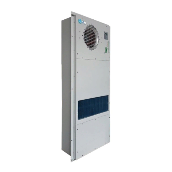
Installation & Operation Manual
Cabinet Climate Control Heat Exchanger
Models EX04CDHC1A, EX08CDHC1C, EX12CDHC1B & EX18CDHC1A
Products Recognized for US and Canada
Industrial Climate Engineering
Division of AIRXCEL
, Inc.
®
®
P.O. Box 5104 • Cordele, Georgia 31010
2002 Hoover St. • Cordele, Georgia 31015
(229) 273-9558 • Fax (229) 273-5154
E-mail: icesales@airxcel.com • Internet: www.acice.com
The most current version of this manual can
1
ICE EX04-18 Heat I&O Manual 06/2020 Rev.1
be found at www.acice.com.
Part Number 03814
Advertisement
Table of Contents

Related Manuals for Airxcel EX04CDHC1A

Summary of Contents for Airxcel EX04CDHC1A
- Page 1 Installation & Operation Manual Cabinet Climate Control Heat Exchanger Models EX04CDHC1A, EX08CDHC1C, EX12CDHC1B & EX18CDHC1A Products Recognized for US and Canada Industrial Climate Engineering Division of AIRXCEL , Inc. ® ® P.O. Box 5104 • Cordele, Georgia 31010 2002 Hoover St. • Cordele, Georgia 31015 (229) 273-9558 •...
- Page 2 Used to point out helpful suggestions that will result in improved IMPORTANT installation, reliability or operation. SPECIFICATIONS SUBJECT TO CHANGE WITHOUT NOTICE. © 06/2020 Industrial Climate Engineering Div. Airxcel , Inc. ® ™ ICE EX04-18 Heat I&O Manual 06/2020 Rev.1...
-
Page 3: Table Of Contents
WARNING • If the information in these instructions are not followed exactly, a fire may result causing property damage, personal injury or loss of life. • Read all instructions carefully prior to beginning the installation. Do not begin installation if you do not understand any of the instructions. •... -
Page 4: Chapter 1: Description & Specifications
Chapter 1: Description & Specifications 1.1 Foreword Note: All operation of this unit shall be performed by qualified persons such as engineers and technicians. This manual shall only be used as the guide for the installation and operation of the ICE EX Series Cabinet Climate Control Units. -
Page 5: Features
1.3 Features • High reliability • Intelligent control • Frequency regulated and energy-saving. • Dry contact and RS485 intelligent communication interface 1.4 Standards Standard Description IEC61000-4 Electromagnetic Compatibility IEC335-1 Safety of household appliances or similar electric appliance GB4798.1 Environmental conditions existing in the application of electric and electronic product –... -
Page 6: Mechanical Installation Of The Heat Exchanger
2.3 Mechanical Installation of the Heat Exchanger Do not press on the heat exchanger cooling fins during installation - this will damage them. If the heat exchanger fins are damaged, repair them before moving it. The mounting flange is factory installed. Ensure the waterproofing seal is in place before installing the unit. -
Page 7: Monitoring
DC Power input: If the unit using -48V DC power input, the connection diagram is shown in Figure 2.2. please be sure to connect power supply in accordance with instructions. Figure 3. DC Power Input Wiring Diagram 2.6 Monitoring IMPORTANT Please refer to the specific wiring definition mark on the unit. -
Page 8: Installation Checklist
Figure 5. DC Input Connection Interface 2.8 Installation Checklist Use the following checklist when the electrical connections and the heat exchanger installation are completed. 1. Check the packing list to ensure no parts are missing. 2. No apparent obstacles near the interior and exterior air flow passages. 3. -
Page 9: Heating Control
Parameter Default Value Setting Range Units Description Refrigeration Point [15 ~ 50] ºC External fan stop point CoolΔT [6 ~ 30] ºC External fan setting range Table 3. Cooling Set Point Parameters 3.2.2 Heating Control Heating startup point = Heating on point - Heating sensitivity. In order to protect the internal equipment, when the internal temperature below the heating on setting point, the unit begins heating, when the cabinet temperature is higher than heating off point, heater stops operating. -
Page 10: Self Test
3.6 Self-Test The unit provides the self testing function for the onsite test. The self testing procedures are as follows: 1. The indoor fan speed 50% run 30 seconds. 2. The indoor fan speed 100% run 30 seconds. 3. The external fan speed 50% run 30 seconds. 4. -
Page 11: Chapter 4: Maintenance
The factory default operation password of the unit is “0001”. To change it, press ENTER on the normal display interface to enter the password input interface, press the LEFT button or RIGHT button to select the digits to change, and press the UP/DOWN button to change the relevant digits, and finally press ENTER button to confirm the change. -
Page 12: Fan
4.2 Fan If a fan fails, the fan can be replaced after dismounting the service panel. Using only Industrial Climate Engineering spare parts to prevent any incompatibilities. Check the weather seals after replacing the fan. Service procedure: 1. Make sure all the power have been disconnected; 2. -
Page 13: Maintenance Checklist
4.6 Maintenance Checklist Date: ________________________ Maintenance Technician: ___________________ Equipment Type: ______________ Equipment Serial Number: __________________ Number Description Result Comment Input voltage is normal Sensor location is reasonable Filter is not dirty heat exchanger is not dirty Check whether there are loose all the lines Unit have no abnormal noise Fan have no unusual noise Drainpipe is not dirty block...
Need help?
Do you have a question about the EX04CDHC1A and is the answer not in the manual?
Questions and answers