Advertisement
HiFi Hospital
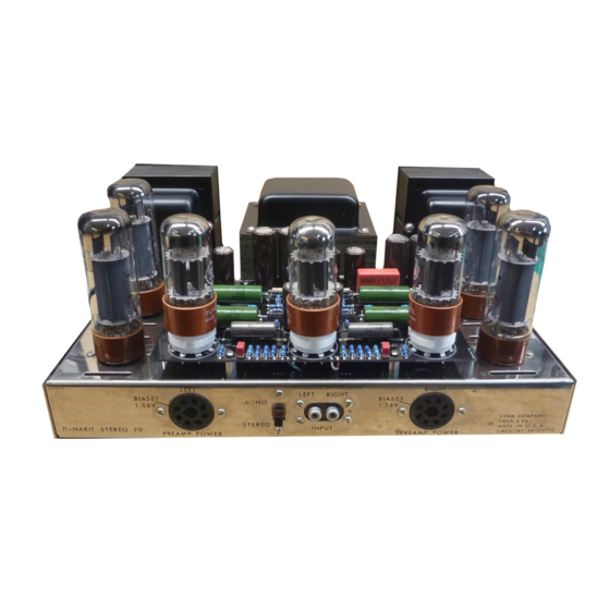
Kit # 79-001
Dyna Stereo 70 Original Replacement PCB
INTRODUCTION
Congratulations on your purchase of HiFi Hospitals' Dyna Stereo 70
original replacement PCB. This kit has been designed with the "beginner" kit builder in mind, if
at any point, this kit appears to be getting "too involved", PLEASE, do not hesitate to call us. This
kit has been designed to restore a Stereo 70 to its original, "factory new" (better than new)
performance.
HiFi Hospital has taken special care in providing a complete step-by-step
comprehensive instruction manual to ensure proper assembly (#79-001-KIT) and installation of
this PCB.
DESCRIPTION
HiFi Hospitals' 79-001 original replacement PCB is a direct replacement
for the original PC-3 PCB. This replacement PCB is superior to the original in all regards
including fiberglass FR-4 construction; double sided plated through copper with solder mask and
silkscreen. Other components include ceramic tube sockets, Sprague '715' series "Orange Drop"
and silver mica capacitors, in addition, all one-watt resistors have been upgraded to 5% two-watt
metal oxide resistors.
INSPECTION
Upon receiving your new kit, it is important that you identify and verify all
parts have arrived, and are in good condition and have not been damaged during shipping.
Included in this kit are one (1) #79-001 PCB with all components, one (1) instruction manual, and
rosin core solder. Two (2) 7199 tubes and tool kit are optional and NOT supplied with the
standard "#79-001" kit.
REQUIRERD TOOLS/ GENERAL WIRING PRACTICES
If you did not purchase the tool kit, you will need a few basic tools:
#2 and #1 flat blade screwdrivers
#2 and #1 Philips screwdrivers
Wire strippers
Sharp-nosed pliers
25-watt soldering iron with standard tip. (DO NOT USE a SOLDER "GUN"!!)
Wiring and soldering practices:
If you feel uncomfortable or are unfamiliar with electronic soldering we highly recommend having
a professional or qualified person install this kit. HiFi Hospitals' staff is also available to perform
this service at an additional $50.00 charge + shipping.
DISASSEMBLY
In the following steps "( )" check off parenthesis are provided for the step-by-step disassembly.
(
) Remove the four (4) screws on both sides of chassis holding top and bottom covers to
chassis.
( ) Remove all tubes. Place tubes in a safe location until final assembly.
Advertisement
Table of Contents

Summary of Contents for DYNACO Dyna Stereo 70
- Page 1 Dyna Stereo 70 Original Replacement PCB INTRODUCTION Congratulations on your purchase of HiFi Hospitals’ Dyna Stereo 70 original replacement PCB. This kit has been designed with the “beginner” kit builder in mind, if at any point, this kit appears to be getting “too involved”, PLEASE, do not hesitate to call us. This kit has been designed to restore a Stereo 70 to its original, “factory new”...
- Page 2 The following steps require the use of a soldering iron. In the following steps, disconnect the wires at the PCB end only, after unsoldering, bend wires away from PCB to avoid burning the wire insulation with soldering iron. Avoid sharp bends to prevent breaking wire. (If wires appear to be brittle, it is highly recommended that they be replaced with pre-tinned #20-#22AWG stranded wire).
- Page 3 ) Using a small screwdriver, remove the four (4) screws securing the “PC-3” circuit board to chassis, carefully remove old circuit board. REASSEMBLY ) Using a small screwdriver, install new circuit board (79-001A) from BOTTOM SIDE of chassis, orient circuit board so C2 and C8 face front of amplifier and C1, C9 face output transformers.
- Page 4 ( ) Using a soldering iron, connect wire from left speaker output terminal strip to eyelet #12 on PCB. ( ) Using a soldering iron, connect wire from right speaker output terminal strip to eyelet #13 on PCB. ( ) Using a soldering iron, connect wire from V3, pin #4 to eyelet #14 on PCB. ( ) Using a soldering iron, connect wire from V4, pin #6 to eyelet #22 on PCB.
- Page 5 PRELIMINARY RELEASE...
- Page 6 PRELIMINARY RELEASE...
Need help?
Do you have a question about the Dyna Stereo 70 and is the answer not in the manual?
Questions and answers