
Summary of Contents for AT GP2
- Page 1 GP2 Data Logger and Controller Research-grade logger controller - capable of complex calculated measurements and advanced feed-back control User Manual version 3.0 Delta-T Devices Ltd...
-
Page 2: Table Of Contents
APPENDIX 5: DL-MKT UNIVERSAL DATA LOGGER MOUNTING KIT ......22 APPENDIX 6: M-ENCL-B2 ENCLOSURE WITH MODEM GATEWAY TO DELTALINK CLOUD........................22 APPENDIX 7: MAKE SURE THE GP2 IS PROPERLY SEALED........24 GP2 SPECIFICATIONS ..................... 25 PRODUCT CARE AND MAINTENANCE ..............33 GP2 CALIBRATION CERTIFICATE ................ -
Page 3: Unpacking
Unpacking The GP2 package contains: • GP2 Logger (with 6AA batteries to be fitted by the user) • GP2-USB USB cable for GP2 • This GP2 User Manual • Screwdriver and cable gland spanner Accessory Options GP2-RLY Relay Expansion Module - 4 extra relays... -
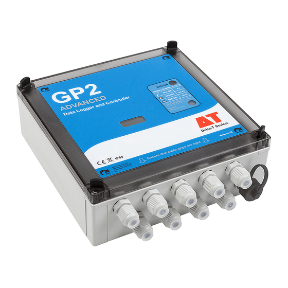
Page 4: Overview
Two banks of terminals provide a 3V precision reference, or unregulated power for sensors. There is also one 5V and one 12 V power terminal. Each sensor can be read at a different rate, from 1 second to >1000 days. •... - Page 5 Layout Reset Internal Battery 6 long life alkaline 1.5V button connector AA/LR6 battery cells Space for Relay Expansion Board Counters Relays +12V SDI-12 9 cable Signal input terminals Signal input terminals glands for for analogue channels for analogue channels M12 connector for 3-6mm dia.
- Page 6 No flash means not logging or no battery power. If the logger locks up, briefly press the Reset button. After pressing Reset, 4 LED flashes indicate that the GP2 is doing a warm reset. Your program and data are preserved and logging will resume.
-
Page 7: Install Deltalink
• One free USB or RS232 port • Internet connection for software install • GP2 to PC USB cable (supplied with GP2) or GP2 RS232 cable The following are also useful • Acrobat Reader for .pdf documents (free from www.adobe.com) •... -
Page 8: Sources Of Help
These tutorials show the progressive development of a soil moisture sensor program, followed by its use to control soil moisture using an irrigation control relay. Run DeltaLINK at the same time and see if you can reproduce the instructions along with the instructor. -
Page 9: Create A Simple Program In 6 Easy Steps
Create a Simple Program in 6 Easy Steps Before you start you need to have DeltaLINK connected to your GP2 (see above), or to the GP2 Simulator (see below). Select Program Select Change Click on “Click to add new item, under Measurement... -
Page 10: The Gp2 Simulator
Select Connection Details, Add and on the Connection Properties, Connection tab set Connect to logger using to Simulator b) On the Details tab set Select simulator model to GP2 simulator. 2) Click on OK, then OK again to connect... -
Page 11: Sample Programs
4. To Start Dataset Import Wizard: Start Excel, select Import Dataset(s) and follow the on-screen instructions. Note: The GP2 memory can exceed the 65,000 row limit of Excel prior to Excel 2007. If so, either update Excel, or import the data into multiple worksheets. -
Page 12: Appendix 1: Gp2 Relay Expansion Module
Each relay is protected from overvoltage and overcurrent using a resettable fuse that will activate at 1A. The relays can handle up to 24V AC or 32V DC . The relay expansion module fits onto the ‘EXPANSION BOARD’ position on the GP2 PCB (as shown below). - Page 13 RELAY 6 Note: All ‘Pwr’ and ‘Ret’ terminals are joined together on the circuit board Power should not exceed 1A at 32V DC or 26V AC DO NOT CONNECT 110V or 240V MAINS POWER TO THE RELAY How to Control the Relays To instruct the relays to switch on or off you need to set up suitable ‘control’...
- Page 14 Connect to pump positive (+) wire Ret: Not used Connect the pump negative (-) wire directly to the power supply negative (–) terminal. ** DO NOT CONNECT 110V or 240V MAINS POWER TO THE RELAY ** Appendix 1: GP2 Relay Expansion Module Page 14...
- Page 15 Figure A3: Switching in a solenoid valve using a common power supply through relay number 1 on the main PCB. *Warning: The relay only can take up to 1A at 24V AC or 32V DC. ** DO NOT CONNECT 110V or 240V MAINS POWER TO THE RELAY **...
-
Page 16: Appendix 2: Gp2 Network Cabling
Appendix 2: GP2 Network Cabling Figure A4 A network of 7 GP2 loggers connected to a PC via a total 100m of EXT/5w-xx extension cables and seven M12 5-way T-Piece connectors. This is the maximum number of loggers and maximum cable length supported. - Page 17 A mini USB cable (not shown in Fig A5) - is required in order to configure • the modem at the logger end. This is supplied as standard with the Delta-T modem solutions i.e. 3G-DLC-BX1/B and MD-3G-DLC. Seven is the maximum number of loggers which can be supported on a •...
- Page 18 Creating a Network Connection Connect your PC to the GP2 network, via the GP2 USB cable or GP2- RS232 cable, or, if using a modem, via the cabling indicated in Figure A5.. Start DeltaLINK. Select Connection Details to display a window listing all (known) logger connections.
- Page 19 Figure A7 Example showing how DeltaLINK displays connections to GP2 loggers on the network connected to a PC on COM Port 3 How to find your USB COM port Start here Click to create a new connection Click to detect...
-
Page 20: Appendix 3: Cable Expansion Lid
Appendix 3: Cable Expansion Lid Note: The GP2 case has 9 cable glands for 3-6 mm diameter cables. Additional and/or larger cables can be fitted using this expansion lid. GP2-G5-LID This GP2 lid has 5 general purpose cable glands. Each gland can accept either a cable with an outer diameter of 3 to10mm diameter, or it can take 2 cables of diameter 3 to 4.5mm - using a... -
Page 21: Appendix 4: Ws-Can Canopy
Appendix 4: WS-CAN Canopy Parts Logger DL2e Logger Assembly Appendix 4: WS-CAN Canopy Page 21... -
Page 22: Appendix 5: Dl-Mkt Universal Data Logger Mounting Kit
The Universal Mounting Kit is a 2mm thick flat stainless-steel plate with U-bolts suitable for attaching to a 42 mm (1⅝ inch) diameter vertical pipe or post and with nuts and bolts for GP2, GP1 and DL6 loggers. Appendix 5: DL-MKT Universal Data Logger Mounting Kit... -
Page 23: Appendix 6: M-Encl-B2 Enclosure With Modem Gateway To Deltalink
The enclosure is designed for use with the standard Delta-T M2 2m mast. It is an alternative to the weather station canopy and provides greater weather protection, electrical shielding, and security for GP2 logger and its related accessories. Weatherproof to IP54 standard •... -
Page 24: Appendix 7: Make Sure The Gp2 Is Properly Sealed
If possible use sealed connectors and mount the logger vertically with the cable glands facing down. Appendix 7: Make sure the GP2 is properly sealed Page 24... -
Page 25: Gp2 Specifications
GP2 Specifications General Specifications Program repeat Multiples of 1s rate Real time clock ± 1 minutes per month typical, ±5 minute`s per month worst case. (-20 to +60 °C) Communications RS232 115.2kBaud, USB-RS232 adapter cable supplied Networking Up to 7 GP2s on 100 m of network cabling, with optional power... - Page 26 Noise Common mode rejection ratio: >70 dB rejection Common mode range: +3V to -2.5V For Bridge measurements, common mode nulled at +1.5V. Normal mode mains rejection (50/60Hz): 100 - 60dB (0 to 0.1% mains frequency error) Input <2nA typical (-20 to +60°C: <12nA)
- Page 27 * RMS noise, included in offset figure ** Single-ended voltage measurements are subject to further offset errors due to current flowing in signal ground. *** mV per 1V excitation **** GP2 contribution to measurement error only, sensor error is additional GP2 Specifications Page 27...
- Page 28 Accepts logic level (low <0.8V, high >2.4V) or open collector or voltage-free switch closure inputs. SDI-12 sensors Up to 62 SDI-12 sensors See also SDI-12 for GP2 User Manual. WET sensor 1 x WET sensor channel (see footnote 4). Water content, bulk/pore conductivity and temperature.
- Page 29 <10 mA, plus any current supplied to sensors current Backup GP2 draws current from internal battery or external supply, whichever provides the higher voltage, so internal battery serves as backup supply if external power fails. Internal backup capacitor retains program state and maintains the clock for >1 hour for battery change or if both supplies fail.
- Page 30 (GP2 loggers only). Online help Detailed context-sensitive Help and reference. GP2 simulator This can simulate a GP2 which is logging Delta-T sensors and operating irrigation valves in a mid-latitude maritime climate. For experimenting with program outcomes. Command line Downloads and manages logged data and error log.
- Page 31 (limit duration of Active and Rest periods), with optional additional recording while Active, and optional pulsing. Conditions expressed as custom formulae and evaluated at defined repeat rates or on a digital event or on a DeltaLINK button click. Alarms...
- Page 32 Simulator Specifications The simulator assists the development of logging and control programs, simulating a temperate maritime climate at a latitude of 51 degrees North, such as that in the UK. Soil water, nutrient and heat fluxes are simulated. Soil moisture is lost by drainage and by surface evaporation and evapotranspiration - from a spring-sown crop harvested in the autumn.
-
Page 33: Product Care And Maintenance
Keep the cover on and cable glands sealed except when connecting sensors or changing the battery. Logger sealing: See Appendix 7: Make sure the GP2 is properly sealed on page The Service Kit (GP2-SER) contains desiccant, a replacement battery holder, spare M8 connector cover cap &... -
Page 34: Index
Index EXT/5W-xx, 3 EXT/8W-xx, 3 Thermistor, 9 Firmware Upgrade, 7 3V precision reference, 4 GP2 Program Specifications, 31 GP2 Relay Expansion Module, 12 GP2 Simulator, 9 analogue, 3, 4 GP2-G5-LID, 3, 20 Analogue, 6 GP2-NPC, 3 Analogue Accur, 27 GP2-NTP, 3... - Page 35 Network Cabling, 16 Script Editor Specifications, 32 Network Cabling options, 17, 18 sensor Network Power Cable, 3 reading rate, 4 Sensor Power and Warm-up Specifications, 29 Sensors tab, 10 serial, 3 power, 3 serial input, 4 Power, 6 simulator, 4, 32 Power Bank, 6 Simulator, 10 Power supply NOT shared by all the...
Need help?
Do you have a question about the GP2 and is the answer not in the manual?
Questions and answers