Table of Contents
Advertisement
Quick Links
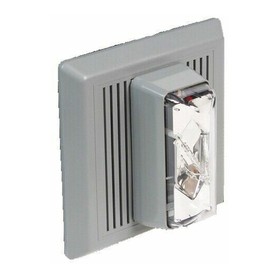
869DSTR*-G1 Diode Polarized Electronic Horn-
Strobe Installation Sheet
Description
The horn-strobes are UL and cUL Listed, high-quality, diode
polarized signals intended for use in general signaling
applications. The strobes flash at 1 fps across their full
operating voltage range.
It is recommended that these products be installed in
accordance with the requirements in the latest edition of
national and local electrical codes.
Table 1: Models
Description
Horn/Strobe, Gray, Flush or Panel Mount, Indoor
*Insert lens color: C - clear, R - red, G - green, B - blue or A - amber
Installation
To reduce the risk of shock, always disconnect all
WARNING:
power before handling the unit.
To reduce the risk of shock, do not tamper with
WARNING:
this device when the signal circuit is energized. Disconnect all
power and wait 5 minutes for stored energy to dissipate before
handling.
1.
Select mounting method as detailed in Figure 1 on page 2
and install the electrical box (not supplied) using suitable
hardware.
a.
For outdoor applications, install the weatherproof box
(ordered separately) using four #10 x 1 1/4" (32 mm)
screws and cap lugs provided in the enclosed parts
bag.
Be sure hook flange is facing outward as shown in
Note:
Figure 1 on page 2.
The designation "TOP" on boxes denotes orientation of
Note:
box after installation.
2.
Attach mounting plate using two #8-32 screws provided
with the surface box (ordered separately) or four #8-32
screws provided with the weatherproof box (ordered
separately). The flush box uses two #8-32 screws (not
provided).
3.
Bring signaling circuit field wiring into electrical box.
© 2011 UTC Fire & Security. All rights reserved.
4.
Ground in accordance with national and local electrical
codes. A green ground screw is provided with both the
indoor and outdoor surface boxes.
5.
Connect signaling circuit field wires to terminals on
horn/strobe assembly (Figure 2 - 4 on page 2).
6.
Mount the horn/strobe assembly on the mounting plate
(Figure 1 on page 2).
a.
Numbers
869DSTR*-G1
b.
c.
7.
Apply power and activate the horn/strobe unit to verify that
it is operating properly.
Selecting the volume and tone
The horn has a jumper for selecting a high or low volume
output level. The default is high volume. To set the output to
low volume, remove the output jumper from the circuit board
on the rear of the unit. See Figure 4 on page 3.
The horn has a jumper for selecting either a temporal or steady
tone. The default is temporal tone. To set the output to steady
tone, remove the tone jumper from the circuit board on the rear
of the unit.
Save the jumper by sliding it onto a single pin.
Tip:
1 / 3
The inside of the top of the grille has hinges that pass
through cutouts and engage with tabs on the
mounting plate. With the bottom of the grille lifted out
slightly, place the grille over the mounting plate so
that the hinges of the grille are in the mounting
cutouts.
Properly seat the grille by pressing the bottom in.
Fasten the bottom of the grille to the mounting plate
by installing the captive combination drive screw.
P/N 3100285 • REV 2.0 • ISS 22JUL11
Advertisement
Table of Contents

Related Manuals for Edwards Signaling 869DSTR-G1 Series


Summary of Contents for Edwards Signaling 869DSTR-G1 Series
- Page 1 869DSTR*-G1 Diode Polarized Electronic Horn- Strobe Installation Sheet Description Ground in accordance with national and local electrical codes. A green ground screw is provided with both the The horn-strobes are UL and cUL Listed, high-quality, diode indoor and outdoor surface boxes. polarized signals intended for use in general signaling applications.
- Page 2 Figure 1: Mounting diagram Figure 2: Typical one-circuit wiring diagram Figure 3: Typical two-circuit wiring diagram Polarity is shown in the active state. Polarity is shown in the active state. (1) From voltage source. (1) From voltage source. (2) To next device or end of line resistor. (2) To next device or end of line resistor.
- Page 3 Figure 4: Jumper setup and terminal block Regulatory information Manufacturer Edwards, A Division of UTC Fire & Security Americas Corporation, Inc. 8985 Town Center Parkway, Bradenton, FL 34202, USA Year of The first two digits of the date code (located on manufacture the product identification label) are the year of manufacture.
Need help?
Do you have a question about the 869DSTR-G1 Series and is the answer not in the manual?
Questions and answers