Table of Contents
Advertisement
Quick Links
Advertisement
Table of Contents

Subscribe to Our Youtube Channel
Summary of Contents for KTR-Group NVT-E Series
- Page 1 KTR-N 42611 EN NVT-E Sheet: 1 of 27 Operating/Assembly instructions Edition: NVT-E Operating/Assembly instructions Drawn: 2019-12-06 Pz/Bet Replacing: KTR-N dated 2019-02-14 Please observe protection note ISO 16016. Verified: 2019-12-06 Pz Replaced by:...
-
Page 2: Table Of Contents
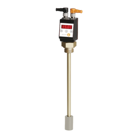
KTR-N 42611 EN NVT-E Sheet: 2 of 27 Operating/Assembly instructions Edition: The level switches series NVT-E serve for monitoring level and temperature in tanks in fluid systems. Depending on the model, the level switches are equipped with a different number of switching outputs. Please find the configuration on the type plate. - Page 3 KTR-N 42611 EN NVT-E Sheet: 3 of 27 Operating/Assembly instructions Edition: Table of contents Operation Diagnosis 4.9.1 Opening the journal 4.9.2 Maximum/minimum filling level 4.9.3 Maximum/minimum temperature 4.9.4 Assigning the switching output for recording 4.9.5 Delay for min./max. saving (filling level) 4.9.6 Delay for min./max.
-
Page 4: Technical Data
KTR-N 42611 EN NVT-E Sheet: 4 of 27 Operating/Assembly instructions Edition: Technical data Technical data Operating pressure: max. 1 bar Operating temperature: -20 °C to +80 °C Ambient temperature: -20 °C to +70 °C Weight: Approx. 400g Density of fluid: Min. -
Page 5: Advice
KTR-N 42611 EN NVT-E Sheet: 5 of 27 Operating/Assembly instructions Edition: Advice General advice Please read through these operating/assembly instructions carefully before you assemble the level and temperature control. Please pay special attention to the safety instructions! The operating/assembly instructions are part of your product. Please store them carefully and close to the level and temperature control. -
Page 6: Assembly
KTR-N 42611 EN NVT-E Sheet: 6 of 27 Operating/Assembly instructions Edition: Assembly The level transmitters are supplied fully assembled and can be fixed to the tank by means of the screw-in thread. Please make sure that the float can move freely and sufficient distance to the tank walls and to other equipment is kept. -
Page 7: Led Status Display
KTR-N 42611 EN NVT-E Sheet: 7 of 27 Operating/Assembly instructions Edition: Operation LED status display Light emitting diodes above the measurement display indicate the status of the switch outputs. The LEDs are assigned to the switching outputs. Table 2 shows the factory settings for the assignment of the switch outputs as level or temperature output. -
Page 8: Button Lock Active
KTR-N 42611 EN NVT-E Sheet: 8 of 27 Operating/Assembly instructions Edition: Operation Button functions To select a menu item and set the values please proceed as follows: • Open the main menu via the button . • Select the submenu via the buttons and and open the submenu via the button . •... -
Page 9: Amendment Of Basic Settings
KTR-N 42611 EN NVT-E Sheet: 9 of 27 Operating/Assembly instructions Edition: Operation Summary of menu The different menu items are not displayed if the option is o__i Configuration Device configuration not available. ▲ Example: With a=0 the menu items for setting the ____ Display analogue output are not available. -
Page 10: Defining Filling Level
KTR-N 42611 EN NVT-E Sheet: 10 of 27 Operating/Assembly instructions Edition: Operation Amendment of basic settings 4.6.1 Defining filling level In this menu the displayed unit symbol for the filling level is defined. b) E F o) u ni Basic EF ►... -
Page 11: Reassignment Of Switching Outputs
KTR-N 42611 EN NVT-E Sheet: 11 of 27 Operating/Assembly instructions Edition: Operation Amendment of basic settings 4.6.3 Reassignment of switching outputs The amendment of assignment of the switching outputs is described here based on the example of switching output 1. b) E F r ) o u_ ____... -
Page 12: Activating/Deactivating Button Lock
KTR-N 42611 EN NVT-E Sheet: 12 of 27 Operating/Assembly instructions Edition: Operation Amendment of basic settings 4.6.5 Activating/Deactivating button lock To prevent unauthorized modifications of settings on the device, it is possible to activate a button lock. b) E F Basic EF ►... -
Page 13: Maximum Displayed Value Of Filling Level
KTR-N 42611 EN NVT-E Sheet: 13 of 27 Operating/Assembly instructions Edition: Operation Amendment of basic settings 4.6.7 Maximum displayed value of filling level The displayed value (upper limit of the measurement range) for the maximum filling level is defined here. b) E F o) H i ____... -
Page 14: Factory Settings
KTR-N 42611 EN NVT-E Sheet: 14 of 27 Operating/Assembly instructions Edition: Operation Amendment of basic settings 4.6.10 Factory settings Definitions of the factory settings set: Switching point / reset point x Delay for switching/delay for resetting for switching output x Maximum and minimum measured value for output Signal characteristics of analogue output Switching characteristics of switching output x... -
Page 15: Switching Outputs
KTR-N 42611 EN NVT-E Sheet: 15 of 27 Operating/Assembly instructions Edition: Operation Switching outputs All switching outputs are set in the same way. Therefore, the number of the switching output is marked with x. Call up the switching output to be set via the menu of the corresponding measurement size ( ____ ____ out _... - Page 16 KTR-N 42611 EN NVT-E Sheet: 16 of 27 Operating/Assembly instructions Edition: Operation Switching outputs 4.7.1 Definition of switching characteristics Window function Function of make contact or break contact defining a signal window. If the measure window is reached, the output signal is set and deleted once it is left.
-
Page 17: Upper Switching Limit (Set Point)
KTR-N 42611 EN NVT-E Sheet: 17 of 27 Operating/Assembly instructions Edition: Operation Switching outputs 4.7.2 Upper switching limit (set point) The upper switching limit for switching output OUT 1 is set in the following submenu: ____ out _ ____ ____ SP1 FH1 F1) H i Meas. -
Page 18: Delay For Set Point
KTR-N 42611 EN NVT-E Sheet: 18 of 27 Operating/Assembly instructions Edition: Operation Switching outputs 4.7.4 Delay for set point The menu Extended functions provides further settings for the switching output x. You can find the submenu on the second submenu level: The delay time for set point and reset point prevents too many false alarms with turbulent conditions. -
Page 19: Testing The Switching Output
KTR-N 42611 EN NVT-E Sheet: 19 of 27 Operating/Assembly instructions Edition: Operation Switching outputs 4.7.6 Testing the switching output Testing the switching output can be started in the following menu: ____ out _ C ) o u_ ____ Meas. value ►... - Page 20 KTR-N 42611 EN NVT-E Sheet: 20 of 27 Operating/Assembly instructions Edition: Operation Switching outputs 4.7.7 Changing display function of status LED The table shows an example with factory settings and with inverted status function for LED3. The switching points are defined as follows: = 70 °C, = 65 °C = 80 °C,...
-
Page 21: Analogue Outputs
KTR-N 42611 EN NVT-E Sheet: 21 of 27 Operating/Assembly instructions Edition: Operation Analogue outputs 4.8.1 Assignment of upper limit The assignment is defined as to which filling level is necessary to display the maximum analogue signal. The setting is made in the following menu: ____ A1) H i ____... -
Page 22: Testing The Analogue Output
KTR-N 42611 EN NVT-E Sheet: 22 of 27 Operating/Assembly instructions Edition: Operation Analogue outputs 4.8.4 Testing the analogue output The analogue output can be tested, too. The highest, the average and the smallest analogue value can be displayed one after another. The setting is made in the following menu: ____ C ) A N _ ____... - Page 23 KTR-N 42611 EN NVT-E Sheet: 23 of 27 Operating/Assembly instructions Edition: Operation Diagnosis 4.9.1 Opening the journal The last 6 incidents recorded of the switching output can be retrieved or deleted here. di A J) o ut ____ Diagnostic ► ►...
-
Page 24: Operation
KTR-N 42611 EN NVT-E Sheet: 24 of 27 Operating/Assembly instructions Edition: Operation Diagnosis 4.9.2 Maximum/minimum filling level In this menu the maximum and minimum filling level saved is displayed or deleted. di A o) M M ____ Diagnostic ► ► Parameter Max/Min Level ___;... -
Page 25: Assigning The Switching Output For Recording
KTR-N 42611 EN NVT-E Sheet: 25 of 27 Operating/Assembly instructions Edition: Operation Diagnosis 4.9.4 Assigning the switching output for recording In this menu the switching output for recording is selected. It is only possible to record one switching output. di A SJ) o u out _ Diagnostic... -
Page 26: Breakdowns, Causes And Elimination
KTR-N 42611 EN NVT-E Sheet: 26 of 27 Operating/Assembly instructions Edition: Breakdowns, causes and elimination The errors listed can only be clues to search for the failures. When searching for the failure the adjacent components must generally be considered. In case of breakdown all outputs are set dead-voltage. The four LEDs are illuminated. The failures are saved in the device until it is switched off. -
Page 27: Spares Inventory, Customer Service Addresses
KTR-N 42611 EN NVT-E Sheet: 27 of 27 Operating/Assembly instructions Edition: Spares inventory, customer service addresses We recommend to store major spare parts on site to ensure the readiness for use of the machine in case of failure of the level and temperature control (NVT-E). Contact addresses of the KTR partners for spare parts and orders can be obtained from the KTR homepage at www.ktr.com.
Need help?
Do you have a question about the NVT-E Series and is the answer not in the manual?
Questions and answers