
Subscribe to Our Youtube Channel
Related Manuals for KROHNE OPTISENS AAC 050 Series


Summary of Contents for KROHNE OPTISENS AAC 050 Series
- Page 1 07/2008 Installation and Operating Instructions OPTISENS AAC 050 Measuring and control instruments for potentiostatic measurements of Chlorine, total Chlorine, Chlorine dioxide, Oxygen, Ozone and Hydrogen peroxide...
-
Page 2: Table Of Contents
Manual OPTISENS AAC 050 Content Introduction......................................4 General ..........................................4 Legal matters ......................................... 4 Safety ............................................. 5 0.3.1 Documentation symbols......................................5 Features ..........................................6 0.4.1 Device ............................................ 6 0.4.2 Controller..........................................6 0.4.3 Connections ........................................... 6 Mechanical installation ..................................7 Installation of panel-mounting converters ................................7 Installation of wall-mounting converters................................. - Page 3 Manual OPTISENS AAC 050 9.2.1 Panel-mounting enclosure ....................................30 9.2.2 Wall-mounting enclosure ..................................... 30 Device return form.................................... 31 Customer settings - for reference ..............................32 OPTISENS AAC 050...
-
Page 4: Introduction
05 / 08 It contains technical information for the installation, start-up and maintenance. If you have any questions not included in this manual please contact your supplier or the official representative of KROHNE Water Solutions in your country. 0.2 Legal matters... -
Page 5: Safety
Manual OPTISENS AAC 050 0.3 Safety Please check for damages immediately after receiving the devices and report any damages within 24 hours to the delivering company. Never work with a damaged device. Keep this manual at a safe place where you can always look up the safety instructions and the information on handling and usage. -
Page 6: Features
Manual OPTISENS AAC 050 0.4 Features 0.4.1 Device Measuring ranges 0.00…4.00 mg/l free Chlorine 0.00…20.00 mg/l free Chlorine 0.00…4.00 mg/l Ozone 0.00…4.00 mg/l TCl2 total Chlorine 0.00…4.00 mg/l ClO2 Chlorine dioxide 0.00…20.00 mg/l Oxygen 0.000…9.999 mg/l Oxygen 0.0…100.0 mg/l H2O2 Hydrogen peroxide Temperature range -30.0…+140.0°C... -
Page 7: Mechanical Installation
Manual OPTISENS AAC 050 1. Mechanical installation On Chapter 9.2 you will find detailed instructions for the installation. For panel-type meters you have to prepare an opening of 92 x 92 mm / 3.6” x 3.6”. Install the device and fix it with the two mounting clips which were part of the delivery. -
Page 8: Installation Of Wall-Mounting Converters
Manual OPTISENS AAC 050 1.2 Installation of wall-mounting converters Unscrew the terminal cover. Drill three holes (max. M5) according to the drawing. Mind that there are two ways for installation: (1) You can hang the device upon the upper screw. In that case drill the upper hole 120mm / 4.7”... -
Page 9: Electrical Connection
Manual OPTISENS AAC 050 2. Electrical connection You will find a detailed connection diagram on the following pages. Before connecting the power supply check the information on the nameplate of the device! Input, output and control lines must be installed separate from each other and separate from power lines! ATTENTION For inputs and outputs use screened lines and connect the screen on one side only. -
Page 10: Connection Diagram Panel-Mounting Converter
Manual OPTISENS AAC 050 2.1 Connection diagram panel-mounting converter Connection Terminals Notes Metal electrodes & 1- 4 1 = screen membrane sensors 2 = measuring electrode without electronics 3 = reference electrode 4 = counter electrode With 2-electrode sensors bridge 3 + 4 Membrane Sensor with 1 - 4 1 + 2 = measurement... -
Page 11: Connection Diagram Wall-Mounting Enclosure
Manual OPTISENS AAC 050 2.2 Connection diagram wall-mounting enclosure Connection Terminals Notes Metal electrode & 1 - 4 1 = screen membrane sensors 2 = measuring electrode without electronics 3 = reference electrode 4 = counter electrode With 2-electrode sensors bridge 3 + 4 Membrane sensors 1 - 4 1 + 2 = Measurement... -
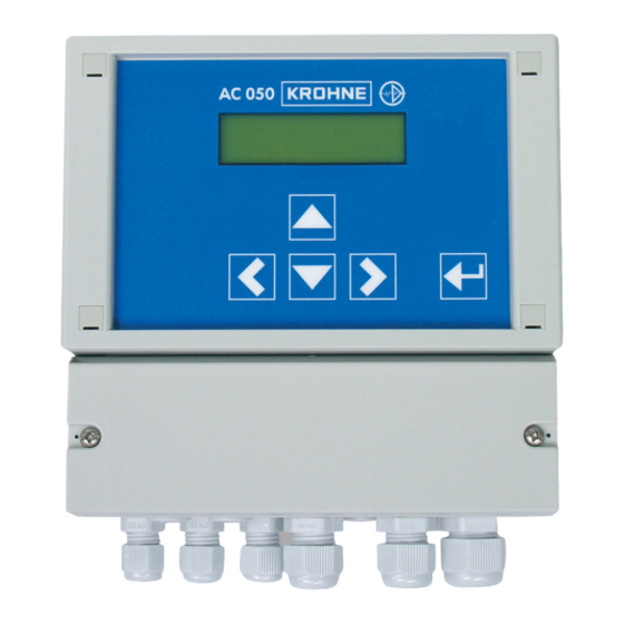
Page 12: Operation Of The Device
Manual OPTISENS AAC 050 3. Operation of the device 1 Measured value 2 Status relay 1 3 Status relay 2 relay OFF relay ON 4 Temperature 5 Controller AUTO: controller ON MAN : controller OFF (manual operation of the relays) 6 Orientation aids 7 Key left ( ) 8 Key up ( ) -
Page 13: Adjustment Of Numerical Parameters
Manual OPTISENS AAC 050 Enter password 1) Address the parameter with key Enter password 2) A double arrow appears behind the number indicating that the number can be changed now with keys Enter password 3) Store the new value with key „Enter“. The double arrow disappears - the new value is stored. -
Page 14: Password And Language
Manual OPTISENS AAC 050 3.3 Password and language Main menu Enter password Enter password 056 Code 3.3.1 Enter password To get access to the various parameters you have to enter the correct password: • Code 11 gives access to the parameters „calibration“, „temperature compensation“, and „set points“. •... -
Page 15: Configuration Of The Converter
Manual OPTISENS AAC 050 4.1 Configuration of the converter Main menu Basic settings Basic settings Configuration Configuration Measurement Temp. Sensor The instruments AC050 POT provide two measuring inputs. Input 1 can work with the following sensors: Parameter Measuring range Free Chlorine 0.00…4.00 mg/l Free Chlorine 0.00…20.00 mg/l... -
Page 16: Temperature Compensation
Manual OPTISENS AAC 050 Main menu Calibration Calibration 8.48 mg/l The Oxygen concentrations in ambient air are stored - You do not need to enter Cal. press ↵ anything. Slope 102% Calibration of the Oxygen measurement The Oxygen measurement is calibrated in water-saturated air. 1) Switch off the controller. -
Page 17: Automatic Sensor Cleaning Asr (Option)
Manual OPTISENS AAC 050 4.4 Automatic Sensor Cleaning ASR (option) Main menu Basic settings Basic settings Cleaning Cleaning Cleaning 1 / day Turn-on delay 6.0 h The patented Automatic Sensor Cleaning ASR prevents staining and passivating coatings and keeps the surface of metal sensors clean throughout the measurement. -
Page 18: On/Off Controller
Manual OPTISENS AAC 050 For any type of controller you have to enter one or two set points, and you have to tell the device whether these set points are reached by increasing or decreasing the measured value. You can choose between three different controller versions: ON/OFF controller The ON/OFF controller switches ON if the measured value exceeds the set point and OFF if it drops back below it or vice versa. -
Page 19: P / Pi Controller As Impulse-Frequency Controller
Manual OPTISENS AAC 050 For an ON/OFF controller you have to set the following parameters: 1) Set points S1 and S2 Set point S1 refers to relay 1, set point S2 refers to relay 2. 2) P range and integral action time for S1 and S2 For an ON/OFF controller set P range = 0 and integral time = 0. -
Page 20: P / Pi Controller As Pulse-Pause Controller
Manual OPTISENS AAC 050 5.3 P / PI controller as pulse-pause controller Main menu Set points and controller versions Set points Set point S1 You can choose 1.50 mg/l Controller settings different controller P range S1 Pulse-Freq. S1 versions for S1 and S2. 0.20 mg/l 00*100/h Integral time S1... -
Page 21: Activation And Deactivation Of The Controller
Manual OPTISENS AAC 050 5.4 Activation and deactivation of the controller The controller is activated and deactivated from the main display without any menus. Press key to switch from Manual Mode (controller OFF) to Automatic Mode (controller ON) and vice versa. The actual mode is indicated in the display. -
Page 22: Manual Operation Of The Relays
Manual OPTISENS AAC 050 5.7 Manual operation of the relays 1.402 mS 25.0°C S2 Auto 1) If the controller is ON, switch it OFF with key Instead of „Auto“ the display shows „Man“. 1.402 mS 25.0°C S2 Man 1.402 mS 25.0°C 2) Switch to the operation mode of S1 with key . -
Page 23: Limit Values
Manual OPTISENS AAC 050 5.8 Limit values Main menu Limit values Limit values Limit S1 Relais 3 is switched ON if the measured value 1.00 mg/l Exceeds limit S1 Limit S2 Relais 3 is switched ON if the measured value 0.30 mgl Drops below limit S2 Turn-on delay... -
Page 24: Alarm
Manual OPTISENS AAC 050 6. Alarm Additional to the limit function the device provides various check functions that raise alarm. In case of an alarm, relay 3 switches, undelayed, and the cause of the alarm is indicated in the display. If the cause of alarm is such that control is no longer possible or might even be dangerous, the controller is automatically deactivated until the alarm is switched off. -
Page 25: Error Messages
Manual OPTISENS AAC 050 6.1 Error messages Error message Cause Action Slope error The slope determined by calibration Please check the sensor connection was higher than 200% or lower than and cable, the flow, and the 20 %. temperature sensor and settings. Then repeat the calibration. -
Page 26: Output
Manual OPTISENS AAC 050 7. Output Main menu Basic settings Basic settings Analog output Analog output Select output Selection 0 – 20 mA - between 0/4 – 20 mA Begin 0/4 mA 0.00 mg/l - of the measured value End 20 mA Corresponding to 20 mA 4.00 mg/l Analog output... -
Page 27: Operation And Maintenance
The device does not require any maintenance. There is no need for readjustment. If you want to have the device checked regularly, you are welcome to send it to KROHNE Water Solutions. Alternatively the device can be checked on site by one of our engineers. -
Page 28: Service
Manual OPTISENS AAC 050 8.7 Service Main menu Unit no. No. 041 Software date M/Y 1.00 Product. date Service Service Product info M/Y 1.00 Analog inputs Analog inputs Input 1 003 Analog inputs Input 2 25.0°C Erase settings Erase settings Press &... -
Page 29: Technical Data
Manual OPTISENS AAC 050 9. Technical data 9.1 Technical data Feature AC 050 P AC 050 W Version panel-type converter wall-mounting enclosure Dimensions (w x h x d) 96 x 96 x 127 mm / 3.8 x 3.8 x 5” 165 x 160 x 80 mm / 6.5 x 6.3 x 3.1”... -
Page 30: Dimensions
Manual OPTISENS AAC 050 9.2 Dimensions 9.2.1 Panel-mounting enclosure 9.2.2 Wall-mounting enclosure OPTISENS AAC 050... -
Page 31: Device Return Form
We cannot service this device unless accompanied by such a form. This means that KROHNE Water Solutions can only service this device if it is accompanied by the following certificate confirming that the device is safe to handle. -
Page 32: Customer Settings - For Reference
Manual OPTISENS AAC 050 11. Customer settings - for reference Identification / location: …………………………………………………. Device Type: ………………. date of installation: ………………. Serial number: ………………. Software version: ………………. Measurement Chlorine (Cl2) Chlorine (Cl2) Total Chlorine Chlorine dioxide 20mg/l (ClO2) 4mg/l (TCl) Oxygen (O2) Ozone (O3) Peroxide (H2O2)
Need help?
Do you have a question about the OPTISENS AAC 050 Series and is the answer not in the manual?
Questions and answers