
Summary of Contents for Power Test Superflow SF-Black Widow
- Page 1 Operator Manual Pub. No.: 180413 Rev.: 4 February 2020 Original Instructions www.superflow.com SF- Black Widow Engine Dynamometer...
- Page 2 Other trademarks and trade names may be used in this document that refer to the entities claiming the marks and names or their products. Power Test, Inc. does not hold any proprietary interest in trademarks or trade names other than its own.
-
Page 3: Table Of Contents
Table of Contents Introduction ........................1 About This Manual ....................1 Target Audience .....................1 Product Features ....................1 Principles of Water Brake Dynamometer Operation ..........2 Safety Guidelines ......................3 At Installation ......................5 During Operation ....................5 Lockout/Tagout Procedures ...................6 System Overview ......................7 Overview ........................7 Dynamometer ......................8 SF-Black Widow .....................8 Date Acquisition ....................10 Components ......................10... - Page 4 Table of Contents Electrical Safety ....................38 Fuses ........................38 Safety Procedures ....................39 Test Preparation ....................40 Mounting the Front of the Engine .................40 Mounting the Engine ....................40 Dyno Shaft Connection ..................41 Engine Water Cooling System ................42 Throttle System ....................43 Sensor Connections .....................44 Stand Connections ....................44 Engine Connections .....................44 Running an Automated Test .................45...
-
Page 5: Introduction
1.0 Introduction 1.1 About This Manual This manual is provided as a reference to explain the operation of the SuperFlow dynamometer system as used on any engine test system and also covers the operation and maintenance of the SuperFlow engine test stand. -
Page 6: Principles Of Water Brake Dynamometer Operation
1.0 Introduction 1.4 Principles of Water Brake Dynamometer Operation An engine dynamometer is a service tool that allows the operator to safely place a controlled load on an engine. A loaded engine test is the only method of verifying engine capability. With the use of a dyno, an engine can be properly operated throughout its power range without being placed into service. -
Page 7: Safety Guidelines
Although the procedures covered in this manual have proven safe in use, Power Test assumes no responsibility for personal injury or damage to equipment resulting from its applications. All operators must be aware that there are several hazards present to anyone in the test cell. - Page 8 • Hot components, water and/or oil. • Do not touch during operation or Contact Power Test if you have any questions while cooling. about the safe operations of our equipment and for • Allow to cool before disconnecting.
-
Page 9: At Installation
2.0 Safety Guidelines 2.1 At Installation WARNING CAUTION • Take care that the dynamometer is not dropped • Do NOT lift the dynamometer by the input shaft. This may damage the dynamometer and or set down sharply. This could cause damage void its warranty. -
Page 10: Lockout/Tagout Procedures
Power Test does not recommend any particular lockout device, but recommends the utilization of an OSHA approved device (refer to OSHA regulation 1910.147). Power Test also recommends the review and implementation of an entire safety program for the Control of Hazardous Energy (Lockout/Tagout). -
Page 11: System Overview
3.0 System Overview 3.1 Overview The WinDyn dynamometer system is an instrumentation package designed for complete test control and data acquisition of an engine or chassis dynamometer. Typical applications include: • Research and development (R&D) • Performance testing • Durability and quality control testing •... -
Page 12: Dynamometer
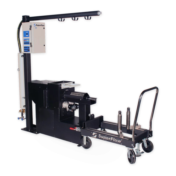
3.0 System Overview 3.2 Dynamometer The dynamometer stand provides all of the connections from the sensors to the data acquisition system and the mount for the power absorber. SF-Black Widow The SF-Black Widow system utilizes a floor-mounted absorber stand and a roll-around engine docking cart to maximize test efficiency in high-volume environments. - Page 13 3.0 System Overview Boom mounted Integrated boom routes water from the sensor box. engine to the cooling tower and organizes transducer cables. Large tool tray. Torsionally compliant dynamometer driveshaft with Heavy-duty drive constant velocity joint. shaft guard. Versatile docking engine cart. Temperature compensated load cell.
-
Page 14: Date Acquisition
3.0 System Overview 3.3 Date Acquisition Components A WinDyn data acquisition system consists of at least two components. They are the sensor system and the computer system. NOTE: Additional options and accessories that can be added to the system are described later in this chapter. -
Page 15: The Computer System
3.0 System Overview The Computer System The computer system consists of a standard computer with up to three monitors installed, a color printer, and WinDyn dynamometer software. Other than the network connection and minimum performance specifications, no special requirements must be met. SuperFlow’s WinDyn dynamometer software was designed for Microsoft Windows... -
Page 16: Sensor Panel Modules
3.0 System Overview Sensor Panel Modules System Interconnect Panel (LEMO) The system interconnect panel provides the primary connection between the sensor box and the peripheral devices (computer, relay box, etc.). The panel also provides connections for some sensor inputs. • Color-coded and keyed LEMO connectors •... - Page 17 3.0 System Overview Thermocouple Input Panel The thermocouple panel provides 16 channels for temperature measurements on the test device. • 16 channels per panel • Type K, (grounded or ungrounded) • Type K thermocouple range, -454° to 2,300°F (–270° to 1260°C), linearized •...
- Page 18 3.0 System Overview Engine Control Panel The engine control panel has five outputs electrically controlled by console switches or by programmed test profiles. Four outputs provide 12V switched DC power for ignition, starter, fuel pump, and auxiliary control. • Internal, automatic reset, 50A thermal breaker on input source, automatic reset, 10-amp polyfuse on ignition output;...
-
Page 19: Accessories And Options
3.0 System Overview 3.4 Accessories and Options A wide selection of additional sensors, adapters, and engine accessories are available. Contact SuperFlow Sales or Customer Service for additional details. Analog Voltage Input Panel The analog voltage panel is an optional accessory that provides up to eight channels of voltage measurements on the test device. - Page 20 3.0 System Overview Fuel System The fuel system consists of a high performance fuel pump and fuel regulators to provide two measured and regulated engine fuel channels. The system is rated up to 800 lbs/hr total delivery with both channels used. •...
- Page 21 3.0 System Overview Oil Coolers A constant engine temperature is vital in dynamometer testing, especially during endurance tests. Figure 3.15 shows a multi-pass heat exchanger with the water inlet controlled by a mechanical thermostat valve. It can be mounted on the absorber stand, the engine cart, or in an alternative convenient location. Figure 3.15: Oil Cooler...
- Page 22 3.0 System Overview Engine Cooling Towers The cooling tower replaces the radiator for water-cooled engines (see Figures 3.16 and 3.17). The thermostat on the cooling tower can be set to control the engine water temperature to a specific setting. The CT700-NOP cooling tower is mounted on the boom support assembly.
- Page 23 3.0 System Overview...
- Page 24 Volumetric Blow-by The JTEC VF563 series flow meter provides exceptional accuracy. The sensor measures the volumetric gas flow by means of vortex sensing. A small strut inside the flow tube creates Karman vortices which are measured by an ultrasonic beam directly across the tube. Because the vortex frequency is only a function of the gas velocity, the detected rate is a direct measure of gas velocity and therefore volume flow.
-
Page 25: Installation
The following is only a suggested room layout. If conflicts arise, local building codes must be followed. Consult your specific room layout drawings for additional details. Contact your Power Test representative should any questions arise concerning the location or installation of your equipment. Dimensions shown are subject to change. -
Page 26: Plumbing Diagram
4.0 Installation 4.2 Plumbing Diagram... -
Page 27: Unpacking
4.0 Installation 4.3 Unpacking The SF-Black Widow system is shipped partially assembled. Some parts are left off for protection during shipping. Interconnect and sensor cables require installation prior to use. 1. Inspect the crates and boxes for external damage. Be sure to check underneath the crate for possible forklift damage. -
Page 28: Absorber Stand
4.0 Installation 4.5 Absorber Stand The SF-Black Widow stand is designed as a docking system with a boom support frame. The boom system keeps all the accessories and engine support lines close and available when needed. The system keeps the test cell safe, organized, and attractive while allowing rapid engine changes. 1. -
Page 29: Cooling Towers
4.0 Installation 4.7 Cooling Towers FROM ENGINE (HOT) The engine cooling tower is mounted on the boom support. The two water hoses (supply and drain) must be connected as shown in Figure 4.6. A thermocouple should be installed on the cooling tower and connected to the Data Acquisition System to monitor and record the cooling temperature with WinDyn. - Page 30 4.0 Installation Figure 4.6 CT700P Pressurized Cooling Tower...
-
Page 31: Computer System
4.0 Installation 4.8 Computer System Communication The computer communicates with the sensor system through an Ethernet Local Area Network (LAN) cable. Connect the Category 5 (Cat-5) network cable from the computer network switch to the RJ-45 connector located on the side of the sensor box labeled Computer Network. -
Page 32: System Interconnect Panel
4.0 Installation System Interconnect Panel The system interconnect panel has connections for several different types of sensors and features plus provides the connections to the console and the computer (Figure 4.8). Figure 4.8 System Interconnect Panel Air 1 SuperFlow airflow measurement turbines are connected to the sensor box system interconnect panel. Use cable 1200A-2044 to connect to the red receptacle labeled Air 1. - Page 33 4.0 Installation Tach/Freq A second SuperFlow air turbine can be connected to the yellow receptacle labeled Tach/Freq if desired. Calibration tables for each flow turbine are entered in the configuration file. Other TTL or MAG frequency devices can be connected here as well but require modification to the definition of channel 12. Engine Speed Other TTL or MAG frequency devices can be connected here as well but require modification to the definition of channel 11.
- Page 34 4.0 Installation Electrical Diagram ...
-
Page 35: Sensor Interconnect Panel
4.0 Installation Sensor Interconnect Panel The sensor interconnect panel (Figure 4.10) provides connections to the primary sensors and controllers on the dynamometer. Figure 4.10 Sensor Interconnect Panel Load Cell 1 Plug the load cell (strain gauge) cable into panel connector marked Load Cell 1. Tach Plug the tach sensor cable into the connector labeled Tach. -
Page 36: Expansion Panels
4.0 Installation Throttle If you have the optional electronic actuator, the throttle connector on the sensor interconnect panel connects to an SF-1805 electric throttle controller or other device using a 0–10VDC control signal. 4.11 Expansion Panels Pressure Connections Connect the hose to the appropriate pressure source. -
Page 37: Thermocouple Connections
4.0 Installation Thermocouple Connections The sensor box temperature panel has inputs CAUTION for up to 16 type K thermocouples. Open-tip thermocouples have a faster response time The standard probe type thermocouples are because of the smaller mass. These are typically designed so they can be bent. -
Page 38: Analog Voltage Expansion
4.0 Installation Analog Voltage Expansion CAUTION This is an eight-channel analog DC voltage input The input circuitry can be damaged if more voltage panel used to integrate exhaust gas analyzers, is applied by the sensor than what the channel is multi-channel Lambda sensors, O2 sensors, designed for. -
Page 39: Throttle System
4.0 Installation 4.11 Throttle System Several styles of throttle control systems are available. The standard system uses a Morse cable. Electric throttle actuators are also available. Due to the variety of fuel supply systems used on today’s engines, you may be required to fabricate special adapters to work with throttle systems. Consult the documentation that accompanied the throttle system on your order. -
Page 40: Initial Check-Out
4.0 Installation 4.12 Initial Check-out After the sensor box is secured and all the cables are connected, the system can be tested for operation. 1. Ensure the power cables for the sensor box are plugged into a suitable power source. 2. -
Page 41: Operation
5.0 Operation 5.1 Introduction WARNING This section describes setting up and running a test Do not attempt to use the dynamometer without on the SuperFlow dynamometer system. proper training from SuperFlow. Severe injury or property damage may result from improper use. 5.2 Safety DANGER WARNING... -
Page 42: Emergency Stop
5.0 Operation An engine test cell can be a dangerous environment. The dynamometer operator will be exposed to a number of hazards. These risks are generally associated with the engine under test rather than with the dynamometer itself and it is thus not possible for SuperFlow to protect the operator against all these hazards by the design of the dynamometer instrumentation system. -
Page 43: Safety Procedures
5.0 Operation Safety Procedures The WinDyn instrumentation system controls the engine and the dynamometer. As a result, there is a possibility that a certain function or equipment is activated at a time when this creates a hazard to a person in the area. -
Page 44: Test Preparation
5.0 Operation 5.3 Test Preparation Prior to the start of dynamometer testing, the entire system should be checked to ensure everything is ready. Some of the items to check are: • Ensure: – The water supply and cooling systems are operational. Top off the water supply tank if necessary . –... -
Page 45: Dyno Shaft Connection
5.0 Operation 7. Roll the Docking Cart into the test cell and dock it with the dynamometer absorber stand. Use the docking clamps and foot brake to secure the cart. 8. Once docked and secured, you may lower the rear support post and remove it if you wish. Dyno Shaft Connection Figure 5.2 Engine Mounted On Cart Figure 5.3 Drive Shaft Connected... -
Page 46: Engine Water Cooling System
5.0 Operation 5.4 Engine Water Cooling System FROM ENGINE (HOT) 1. The thermostat or any flow restrictions should be removed from the engine. The thermostat on the cooling tower will perform the temperature control function. 2. Connect the tower supply hoses to the engine (Figure 5.3). -
Page 47: Throttle System
5.0 Operation 5.5 Throttle System Several styles of throttle control systems are available. The standard system uses a Morse cable. Electric throttle actuators are also available. Due to the variety of fuel supply systems used on today’s engines, you may be required to fabricate special adapters to work with throttle systems. Consult the documentation that accompanied the throttle system on your order. -
Page 48: Sensor Connections
5.0 Operation 5.6 Sensor Connections Stand Connections 1. Place the Air Temperature and Humidity sensor WARNING in a location close to or in the airflow to the engine air intake. Do not put too close to the Always turn the power OFF to engine as heat from the engine could affect the the sensor box when plugging or readings or a backfire from the engine air inlet... -
Page 49: Running An Automated Test
5.0 Operation 5.7 Running an Automated Test Follow this procedure for running each test. Repeatable and accurate test results are obtained by consistent test methods. Quick reference instructions are provided with this manual as a stand alone document that can be placed near the console for easy viewing. Infrastructure and Engine Setup 1. - Page 50 5.0 Operation SuperFlow Technical Support Quick Start Checklist for SF-BW Engine Dynos With NetDyn Step Action Location Purpose Preliminary Water System Dyno cell Insure all infrastructure systems are functional Steps Exhaust System Insure all necessary engine mounting functions are Airflow System completed Mount Engine Power on computer...
-
Page 51: Operator Console And Computer
5.0 Operation Operator Console and Computer Figure 5.7: Operator Console Controls Figure 5.8: Dyno Computer Desktop Use the power switch on the Dyno Computer and the power key switch on the Operator Console to turn both systems ON. The Dyno Computer desktop will show on all screens once the computer operating system has properly loaded. -
Page 52: Test Group Dialog
5.0 Operation Test Group Dialog When WinDyn is loaded, operators will be presented with a blank WinDyn desktop. To begin preparing the system for testing, select and load the appropriate Test Group file. Press the F2 function key to open the Install Test Group window. -
Page 53: Valpos Adjustment
5.0 Operation 6. Click the Specifications tab and enter the engine specs. 7. Adjust the Valpos setting as necessary. 8. Adjust the fuel specific gravity as necessary. 9. Verify all other specification settings. Figure 5.15 Test Setup - Specifications ValPos Adjustment ValPos Adjustment –... -
Page 54: Running A Test
5.0 Operation Running a Test Automated tests are executed from the operator console touch screen or computer keyboard and mouse. The steps below show how to run an Accel Test using the operator console. The following steps assume the Accel Test has been select, WinDyn Software is properly setup, Engine is properly connected to dyno, warmed up and running. -
Page 55: Post Test
5.0 Operation Post Test Each test can be viewed after it is saved. Current data is stored in memory in the Data Acquisition sensor box. Saved data is on the computer in the location and with the filename specified in the Test Setup screen. Press “Shift + F3”... -
Page 56: Analyzing The Test Results
5.0 Operation 5.8 Analyzing the Test Results All automated tests will save the test data automatically on the computer. The recorded data can be viewed, plotted, and printed using the WinDyn Stored Data Viewer. NOTE: Refer to the WinDyn operators manual for more information on how to use the Stored Data Viewer. Double click here to add overlays to your base plot. - Page 57 5.0 Operation DATA SHEET...
-
Page 58: Maintenance
6.0 Maintenance This product is designed to provide years of trouble free service with a minimum amount of regular maintenance. The system should be periodically serviced according to the maintenance schedule below. 6.1 Maintenance Schedule If necessary, the dynamometer can be cleaned using an all-purpose cleaning detergent and CAUTION water. -
Page 59: Preventative Maintenance
6.0 Maintenance WARNING WARNING • Post safety warnings and barricade work AUTOMATIC STARTING HAZARD. area to prevent unauthorized use of the engine connected dynamometer before maintenance has been dynamometer could started completed. remotely dynamometer • Only qualified machine operators equipped with an Air Starter. Ensure maintenance personnel should perform the starting has been disabled prior to procedures covered in this manual. -
Page 60: Calibration
6.0 Maintenance 6.2 Calibration The sensors used with the SF-Black Widow should be periodically calibrated for highest measurement accuracy. Not all sensor channels require calibration. Some, such as thermocouples, are calibrated at the factory and normally do not need re-calibration. Pressure transducers and analog voltages, have the calibration set in the configuration file based on the manufacturer’s specifications. - Page 61 6.0 Maintenance 15. Remove weights and calibration arm 16. Click ‘ZERO’ button again. 17. Click ‘SAVE’ and overwrite existing calibration file by continuing to click ‘OK’ as dialogs appear. 18. Click ‘DONE’ to exit calibration dialog box. Torque calibration is now complete. If the readings do not correspond with the procedure or are not within acceptable limits, contact SuperFlow Customer Service.
-
Page 62: 2640 Circuit Board Leds
6.0 Maintenance Calibration Coefficients: A calibration printout with the coefficient values can be obtained and kept in a log which is useful for documentation and tracking any drift trends in the sensors or changes in the channel definitions. Performing a current value calibration creates a new coefficient number for that channel or channels. All other channel coefficients should remain the same. -
Page 63: Servo Valve Indexing
6.0 Maintenance 6.4 Servo Valve Indexing The following procedure will describe the correct way to index the servo valves (inlet and outlet) on the SF-Black Widow model dynamometer. This process is required anytime you replace or repair either servo valve or their associated servo controller circuit board. 1. - Page 64 6.0 Maintenance 3. Position the valves on the tool tray on the engine stand so you can observe the movement of the valves. Reconnect each valve’s cable. 4. Power up the system. Load the Diag_BW test group. Set the console LOAD control mode to MANUAL and 0%.
- Page 65 6.0 Maintenance 7. GROSS ADJUSTMENT PROCESS: Loosen the set screws on the valve. Confirm that the valve you are indexing is at 0% on the screen. Rotate the valve slowly independent of the shaft until the sharp edge of the valve spool is lined up on the very edge of the window. Dap the set screws with Loctite 242 and snug them down.
- Page 66 6.0 Maintenance 9. You have now completed the valve opened position adjustment. Now perform the valve closed adjustment. 10. At the console, turn the load knob to 100%; confirm ServIn and ServOt are at the 100% position on the screen. 11.
- Page 67 6.0 Maintenance...
-
Page 68: Troubleshooting
7.0 Troubleshooting This section outlines basic procedures to follow if the component or instruments do not function properly. Contact SuperFlow Technical Support if you have any questions about the safe operation of the equipment or for service and advice. WARNING WARNING AUTOMATIC STARTING HAZARD. -
Page 69: Automated Test Mode
7.0 Troubleshooting 3. Select MANUAL control mode on the small touch screen on your console. 4. Turn the load control knob up and down, from 0% to 100% and observe those screen objects move from 0-100% 5. Now have someone else turn the knob and go into your dyno cell and observe the valves themselves inside the engine stand and see if they are indeed moving when the operator turns the knob. -
Page 70: Control Electronics
7.0 Troubleshooting 7. Quit the test. 8. If the valves check out, then you know they are at least capable of moving. That checks out most of the electronics. 9. Your valves still may not be indexed properly. Indexing SF-Black Widow servo valves is addressed in a separate procedure that can be obtained from SuperFlow Customer Service. - Page 71 7.0 Troubleshooting board to determine whether the board is for an inlet or an outlet valve. If you receive a replacement board from SuperFlow, you must insure the jumpers are installed correctly for the location where you plan to use the board (inlet or outlet valve).
-
Page 72: Servo Valve Diagnosis
7.0 Troubleshooting Servo Valve Diagnosis: During the manual sweep test, not only should the valve sweep evenly, but it is sometimes helpful to put your hand on the servo and feel the little ticks as it rotates. The ticks should be even without any stutter. If the stutter happens at even increments, like every 4th one, then it is likely that it is a motor problem, or every 16th one, then it is likely an electronics problem. -
Page 73: Absorber
7.0 Troubleshooting 7.2 Absorber The SuperFlow SF-Black Widow absorber is a very robust and durable piece and rarely fails mechanically. If your servo valves check out good mechanically and electrically, then the next step is to have a look at your absorber. - Page 74 7.0 Troubleshooting The troubleshooting tips in the following table may also help diagnose a servo valve or absorber problems. Troubleshooting Chart Symptom Possible Cause Absorber does not load • Insufficient water supply • Servo Valve spool loose or incorrectly indexed •...
-
Page 75: Water System
7.0 Troubleshooting Troubleshooting Chart Symptom Possible Cause Control unstable • Bad RPM signal (EngSpd mode); RPM • Servo Valve spool loose or incorrectly indexed rate inconsistent with • Check inlet/outlet water temp delta T; optimum delta T is 60-100 degrees F selected rate - continued Absorber loses load •... -
Page 76: Appendix
8.0 Appendix The following pages contain information specific to the SuperFlow SF-Black Widow dynamometer. As specifications and part numbers change, these documents will be updated to reflect the equipment and requirements for your machine at the time of shipment. Contact your sales representative for further...
Need help?
Do you have a question about the Superflow SF-Black Widow and is the answer not in the manual?
Questions and answers