
Summary of Contents for Nissei GTR-AR
- Page 1 Battery powered driver SD type Instruction Manual <Read this manual before using the product.> NISSEI CORPORATION...
-
Page 2: Introduction
Introduction Thank you very much for purchasing our product. Safety Precautions ・Be sure to carefully read the contents described in this instruction manual and to understand how to use product correctly before using it. ・The extent of hazard/damage expected to occur in the case of improper handling are classified and indicated in ranks of “DANGER”, ”WARNING”, and ”CAUTION.”... - Page 3 Warning ■General The operators in charge of installation, piping, wiring, operation, handling, maintenance, and inspection should have enough knowledge and technical skill related to the product. Failure to follow this precaution may result in fire, electric shock, injury, and/or damage to the application. Do not repair, disassemble or remodel the product.
- Page 4 Caution ■Installation Do not put any combustible material near the product. Failure to follow this precaution may result in fire. Do not put any object that may prevent air from being circulated around the product. Failure to follow this precaution may cause burns due to abnormal overheating, and/or fire. Do not allow any foreign materials to enter the driver.
-
Page 5: Table Of Contents
Table of contents Introduction Safety precautions 1. Part number and Model Configuration P.6 2. Section Names P.7 3. External Dimensions P.10 4. Installation P.11 5. Wiring Diagrams P.12 6. External I/F Specifications P.16 7. I/O Terminal Wiring P.18 Control input P.19 Control output P.19... -
Page 6: 1. Part Number And Model Configuration
Make sure the Driver Model on nameplate is consistent with your order. Motor ー Series Motor Ver Motor power Voltage Auxiliary code classification ー Series GTR-AR Motor Ver Brushless Motor SD type Motor classification Common to Motor and Brakemotor Motor power 0.75kW Voltage DC48V Empty Standard specifications Auxiliary code... -
Page 7: 2. Section Names
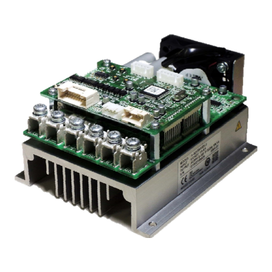
2. Section Names Name Name Main circuit terminal block (M5) Nameplate(attached to the side face) Mounting hole Heat Sink Connector for control signal (CN1) Built-in trimmer 3 (VR3) Status display LED lamps 1 ~ 3 Built-in trimmer 4 (VR4) (red/yellow/green) Connector for communication (CN8) Built-in trimmer 2 (VR2) Connector for motor signal (CN6) - Page 8 ■Built-in switch When you enter a control signal, choose to use internal power supply(+15V) or external power supply. Code Setteings Description External power supply Disconnect from the internal power supply. (Default) Internal power supply Add 15V to each input terminal I1~I8. 【Setting Built-in Switch(SW1)】...
- Page 9 ■Built-in trimmer There are four built-in trimmers on the driver. The following settings can be changed by adjusting the trimmers. Code Function name Description Default Turning the trimmer clockwise increases the speed. *1 Built-in trimmer 1 Speed Range: 0 ~ 4000 [r/min] Full (Speed Control) The maximum speed value for this trimmer can be changed with...
-
Page 10: 3. External Dimensions
3. External Dimensions ■A-SDNB080L4 Approximate Weight=0.73kg... - Page 11 4. Installation ■Installation Environment Ambient Temperature -10~50℃ Ambient Humidity 95%RH or less (no condensation) Altitude 1,000m or lower A place with no corrosive/explosive gas, vapor, etc. Atmosphere A well-ventilated place without any dust. Vibration 2.0G or less Installation Place Indoors *When installing the driver, place it in a switchboard or the like to prevent foreign materials from entering.
-
Page 12: 5. Wiring Diagrams
5. Wiring Diagrams When using external ■Sink connection example (when using external power supply) power supply (O) When using the external power supply, When using internal set the built-in switch lever of the driver (SW1) as shown on the right. power supply (I) Built-in switch (SW1) +... - Page 13 When using external ■Source connection example (when using external power supply) power supply (O) When using the external power supply, When using internal set the built-in switch lever of the driver (SW1) as shown on the right. power supply (I) Built-in switch (SW1) +...
- Page 14 When using external ■Sink connection example (when using internal power supply) power supply (O) When using the internal power supply, When using internal set the built-in switch lever of the driver (SW1) as shown on the right. power supply (I) Built-in switch (SW1) +...
- Page 15 ■Caution for Wiring When the TGND and main power supply(-) are connected outside of the driver, the current flows in both the main power supply(-) and TGND side. Each current value depends on the wiring resistance. In case of flowing the current over 2A in the TGND side, it may cause damege to the driver and control device. Wire with the following conditions.
-
Page 16: 6. External I/F Specifications
6. External I/F Specifications I/F is not isolated from the main power supply. Pay extreme attention when wiring. ■Connector specifications Code Manufacturer Type Remarks Terminal block Tightening torque︓1.6 ~ 2.0 N·m (M5) (TM1 ~ 6) Applicable housing: PUDP-22V-S J.S.T.MFG.CO.,LTD. S22B-PUDSS-1 Applicable crimping terminal: SPUD-001T-P0.5 Applicable housing: XAP-05V-1 J.S.T.MFG.CO.,LTD. - Page 17 ■I/O connector pin arrangement(CN1) Terminal #1 notch ■Layout of motor signal connector (CN6) *1 Terminal No. Terminal name Function name +15V Power supply 15 V HALL_U Hall sensor input U-phase HALL_V Hall sensor input V-phase HALL_W Hall sensor input W-phase Ground *2 *1 The maximum extension length is 5 m.
-
Page 18: Control Input
7. I/O Terminal Wiring 7-1 Control input ■When using external power supply(set SW1 to the side of external power supply(O)・default *1) 【Sink connection】 【Source connection】 5.1kΩ 2〜9 I1〜I8 5.1kΩ 2〜9 I1〜I8 External External power 2kΩ power supply 2kΩ supply +12 ~ 24 V 1... -
Page 19: Control Output
7-2 Control output ■Maximum rated value of control output Max voltage between C and E C1/E1, C2/E2 100mA Max current C3/E3, C4/E4 50mA External 【Sink connection】 【Source connection】 External power supply power supply Load C1〜C4 C1〜C4 10,12,14,16 10,12,14,16 11,13,15,17 11,13,15,17 E1〜E4 E1〜E4 Load... -
Page 20: 8. User Constants
8. User Constants 8-1 Setteing of Constants The user constant can be changed using PC software “ACD-PSTool.” * “ACD-PSTool” can be downloaded from our website for free. * The communication cable between PC (RS-232C) and the driver is an optional accessory (sold seperately). ■The “ACD-PSTool”... - Page 21 Name Description Unit Initial value Attribute Setting range Sets the acceleration time 2 which is from Pn023 Acceleration time 2 0 [r/min] to the acceleration/deceleration 0.00~5.00 time standard speed (Pn025). Sets the deceleration time 2 which is from Pn024 Deceleration time 2 the acceleration/deceleration time 0.00~5.00 standard speed (Pn025) to 0 [r/min].
- Page 22 ■I/O function constants Name Description Unit Initial value Attribute Setting range Pn100 Select the function of input terminal 1. 1~12 I1 input function selection ― Pn101 Select the function of input terminal 2. 1~12 ― I2 input function selection Pn102 Select the function of input terminal 3.
- Page 23 ■Comparison constants (for output function) Name Description Unit Initial value Attribute Setting range Current limit value Sets the current value (rated current ratio) Pn151 upon direct current when the direct current lock function is 0~100 lock activated. Sets the current value (rated current ratio) Torque detection Pn160 to turn ON the specified excessive torque...
- Page 24 ■Gain constants Name Description Unit Initial value Attribute Setting range Sets the rigidity table. After the setting is completed, the following constants will be changed to the setting values in each Pn200 Rigidity table table. ― - Speed control proportional gain (Pn201) - Speed control integral time (Pn202) - Torque filter time constant (Pn203) Speed control...
-
Page 25: Constants Explained
8-3 Constants explained ■Constants related to command settings Pn000 Speed command source selection Pn001~Pn008 Speed command 1 ~ 8 Sets the speed command to the motor. Select speed commands 1 ~ 8 by the multi-function input (speed command selection 1 ~ 3). * Refer to the explanation of Pn100 ~ 107 and Pn110 ~ 117 for detailed settings of the multi-function input. - Page 26 Pn000 sets the command source when all of speed command selection 1 ~ 3 are set to OFF. * When the command value reaches 3000 r/min, the motor is operated with 3000 r/min as the upper limit of the rotation speed. Setting Speed command Description...
- Page 27 【Speed setting examples】 Examples of speed commands set by input terminals (speed command selection 1 ~ 3) are listed below. Speed commands by external analog terminal voltage and digital speed commands set to user constants can be used selectively by switching input terminals. Commanded speed User constant setting [r/min]...
- Page 28 Pn020 Acceleration/deceleration time command source selection Pn021~Pn024 Acceleration time 1 ~ 2, deceleration time 1 ~ 2 Set the acceleration/deceleration time when changing speeds commanded for the motor. The motor can be accelerated or decelerated during any time within the setting range according to the constant and acceleration/deceleration time standard speed settings (Pn025).
- Page 29 Pn025 Acceleration/deceleration time standard speed Sets the standard speed of acceleration/deceleration time. 【Acceleration time】 For the acceleration time, this sets the time required to increase the motor operation speed from the stopped state to the acceleration/deceleration time standard speed (Pn025). When the speed command is lower than the standard speed, acceleration is conducted at the rate from the stop state of the motor to the standard speed.
- Page 30 Pn040 Built-in trimmer 1/PWM speed command standard speed Sets the standard speed of the built-in trimmer 1 and PWM speed command. This will be the maximum speed for clockwise rotation for built-in trimmer 1, and the speed at Duty 100[%] for the PWM speed command. * The speed of up to 5000 [r/min] can be set, but the available motor speed is only up to 4000 [r/min].
- Page 31 ■Constant related to external analog input Pn050 External analog input level Select the external analog input level. 1 : 0V~10V 2 : 0V~5V * When voltage exceeding the selected level is input, the upper limit of the level is regarded as the input voltage. Pn051 Analog input gain Set the gain of external analog input.
- Page 32 ■Constant related to analog output Pn060 Analog output selection Sets the function output from the analog output terminal. Following is the correspondence table of the setting values and the functions. Setting Function Description value Speed Output the actual speed of the motor. Load factor Output the load factor of the motor.
- Page 33 ■Constant related to input terminals I1 ~ I8 Pn100~Pn107 I1 ~ I8 input function selection Sets functions of input terminals I1 ~ I8. Input functions can be assigned to corresponding input terminals I1 ~ I8 by setting I1 ~ I8 input function selection. The PWM speed command and pulse frequency speed command can only be assigned to input terminal 8.
- Page 34 Pn110~Pn117 I1 ~ I8 input polarity selection Polarity of input terminals (I1 ~ I8) can be switched by setting the polarity selection. Set the ON/OFF polarity of each input terminal according to the specifications of the host device. Normally, commands such as the CW driving and CCW driving can be given by connecting input terminals (I1 ~ I8) with COM (when the internal power supply is used).
- Page 35 CW rotation CCW rotation Rotation pulse CW rotation pulse CCW rotation pulse Switched at the first pulse Rotation direction after changing the rotation direction * About pulse waveform The specifications of output pulse is as shown on the right. Select the counter according to the specifications. Fixed to 240 [μs] 20 [μs] or less 20 [μs] or less...
- Page 36 Pn165 Rated torque detection hysteresis width Set the current value to turn OFF the rated torque over output. The value is set as the ratio [%] against the rated current. The value obtained by subtracting the torque detection hysteresis width from the rated torque (100[%]) is the current value to turn OFF the rated torque over output.
- Page 37 Pn173 Mechanical brake operation standby time Sets the operation standby time after the internal commanded speed reaches the mechanical brake operation speed level (Pn171) until the brake control signal is actually turned OFF. Internal speed command Mechanical brake release speed level (Pn170) Mechanical brake operation speed level...
- Page 38 ■Constant related to gain adjustment Pn200 Rigidity table Select the control gain (speed control proportional gain [Pn201], speed control integral time [Pn202] and torque filter time constant [Pn203]) depending on the loaded machine rigidity connected to the motor. Set in accordance with the machine rigidity. The setting values are as listed below.
- Page 39 ■Constant related to safeguards Pn250 Overload selection Selects the method to detect the overload alarm. ※There is no choice for this type. Setting Function Description value Estimates the temperature of the motor according to actual electric current in the Electronic thermal motor as shown below, and issue an alarm when the estimated value reaches the preset temperature.
-
Page 40: Driver Error List And Display Method
9. Safeguards This driver outputs the error detection signal and displays the error state by LED lamps when any problem is detected.(LED 1 (red) lit, LED 3 (green) lit or blinking) When a problem occurs, the motor enters an emergency stop state (free-run state) regardless of operation conditions. -
Page 41: Causes And Countermeasures When Safeguards Are Activated
9-2 Causes and countermeasures when safeguards are activated When the safeguard functions are activated, locate the cause and take necessary countermeasures according to the procedure below. Alarm name Example of causes Countermeasures Load (friction load, inertia load) is large. Check the operation conditions. Overload Check the brake power supply. -
Page 42: Troubleshooting
9-3 Troubleshooting If you experience problems such as motor rotation, please refer to the countermeasures listed below to inspect and resulve the cause of the problem. Be sure that inspections are performed by qualified individuals as improper handling may increase the risk of injury. Symptoms Cause Things to check... - Page 43 10. Specifications Item Description Applicable motor power 0.75kW Output current DC48V 19.5A / 39A (Rated/max) Main circuit/control circuit DC 40~60V input voltage range Rated rotational speed 3000r/min Speed control range 80~4000r/min External analog command, PWM speed command, pulse frequency speed Speed command method command, built-in trimmer 1, speed command 1 ~ 8 Acceleration/...
-
Page 44: 11. Accessories
11. Accessories ■I/O cable (connected with CN1) Description Color IN-COM Yellow Lead wire AWG26 Green - - Orange AOUT TGND Code Manufacturer Type on board side Type on I/O cable side Applicable housing: PUDP-22V-S J.S.T.MFG.CO.,LTD. S22B-PUDSS-1 Applicable crimping terminal: SPUD-001T-P0.5... -
Page 45: 12. Conformity To Safety Standards (Ce, Kc
12. Conformity to Safety Standards (CE, KC) ■Compliance with CE Marking (EMC Directive) This driver is tested in accordance with European standards EN61800-3:2004+A1:2012, and complies with EMC Directive. The following conditions must be met to ensure continued compliance with EMC Directive. ・... -
Page 46: 13. Storage, Warranty
13. Storage, Warranty ■Storage Note the following when storing the product after purchase temporarily or for an extended period of time. ・ Store the product at a well-ventilated place free from high temperature, humidity, dust and metal powder. ■Warranty 1.Warranty period Whichever is shorter of 18 months from the date of delivery or 12 months after start of use. -
Page 47: Contact Us
Contact Us ■Inquiries about quote, purchase, repair, and inspection Overseas Sales Address 1-1 Inoue, Izumi-cho, Anjo, Aichi 444-1297, Japan +81-566-92-5312 +81-566-92-7002 E-mail oversea@nissei-gtr.co.jp... -
Page 48: Related Instruction Manual And Software
Battery Powered Driver SD type Detailed Instruction Manual (this manual) Name Detailed instruction manual for the specialized driver including details of Description parameters, etc. https://www.nissei-gtr.co.jp/pdf/data/gtr/manual/sd/battery-dsd-e.pdf Parameter Setting Software for the Battery Powered Type Driver (ACD-PSTool) Name Parameter setting software for this driver. Description https://english.nissei-gtr.co.jp/gtr/download/agreement-e/... - Page 49 NISSEI CORPORATION 2020/3 Ver 1.0...
Need help?
Do you have a question about the GTR-AR and is the answer not in the manual?
Questions and answers