Advertisement
Quick Links
ISO 9001:2008 CERTIFIED
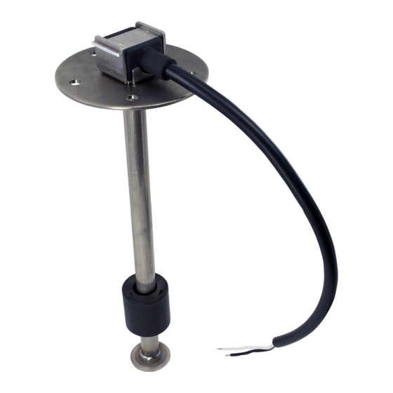
Fuel Level Sender
Installation
Top Mounted
Install using a nitrile rubber gasket. Use # 10-24 screws
(or equivalent) to secure sender head to tank. Torque
screws to 18 in.-lbs. [2.0 N-m] torque.
Maintenance & Quality
As sur ance Considerations
Since this is not a metal to metal joint, the torque and
screw clamp load will naturally relax as the gasket
flows to a normal or prevailing torque condition.
CAUTION: Do not over-torque. Do not re-
torque. Excessive torque/or re-torqu ing may warp
or distort sender head. The gasket underneath
sender heads that are warped during installation or
re-torquing may be over-com pressed and thus, over-
stressed. Pinching or over-stressing of gaskets can
dramatically reduce their service-life and may result
in premature failure (leakage) in service.
Sender Removal Warning
Should it appear necessary, for any reason, to
remove a sender from the tank, do not attempt
removal unless under competent supervision with all
due precautions taken against the hazards of escap-
ing flammable liquid or vapor.
Bottom Mounted
A. Use mounting pad with blind holes.
B. Use mounting bolts with integral O-rings
seals under the heads.
Instructions For Installing &
Troubleshooting Rochester
9800 Series Fuel Level Senders
CAUTION : Read Completely Before Attempting Installation
Ground
Tank Flange Detail
+.030
-.000
ø1.560 [ø39.62]
HOLE
2.125 DIA
BOLT CIRCLE
REF
#10-24 UNC
5 TAPPED HOLES
Sender Electrical Connections
It will be nec es sary to connect one sender wire to a suit-
able grounding point. System voltage should not be
applied to sender. The voltage from fuel level indicator is
current and voltage limited, and incapable of causing
ignition of fuel vapor when sender lead wire is shorted to
ground. The other sender wire must be connected to the
"SEND" terminal of the fuel level indicator.
Wiring
1. Turn ignition switch off.
2. Using insulated 16-gauge wire, connect the ignition
terminal on the indicator to a battery positive source,
usually parallel with the ignition circuit.*
3. Using insulated 16-gauge wire connect sender to sender
terminal on a matched indicator.
4. Using insulated 16-gauge wire establish a ground
connection from sender to ground terminal on the
indicator.
5. Establish ground connection between indicator ground
terminal and ground.
*NOTE: Do not connect the indicator directly to the bat-
tery; connect through a fuse box.
The Measure of Excellence
Fuel Level Indicator
To Fused
Power Source
SEND GND
IGN
12 or 24 VDC
(Depending
Upon Indicator)
Rear
View
(Typical)
Ground
1.876 [47.65]
1.063 [26.99]
.735 [18.67]
1.011 [25.68]
.683 [17.35]
TYP
INDEX (LEAD) HOLE
72°
TYP 2 PL
REF
68°
TYP 2 PL
REF
TANK MOUNTING HOLE
MS-514
formerly
DS-1718
TYP
05/10/2016
Advertisement

Summary of Contents for Rochester Gauges 9800 Series
- Page 1 Instructions For Installing & Troubleshooting Rochester MS-514 9800 Series Fuel Level Senders formerly DS-1718 CAUTION : Read Completely Before Attempting Installation ISO 9001:2008 CERTIFIED Fuel Level Sender Fuel Level Indicator To Fused Power Source SEND GND 12 or 24 VDC...
- Page 2 These instructions were prepared to assist tradesmen and others generally familiar with this type of equipment. Consumers may not be qualified to perform installations. If you have any questions about these procedures, please contact Rochester Gauges for assistance. There are several different styles of sending units. The differences are both external and internal. Be sure you have the correct replacement part number before installation.
Need help?
Do you have a question about the 9800 Series and is the answer not in the manual?
Questions and answers