
Summary of Contents for Furrion FAN73B7C-BL
- Page 1 TV/AM/FM/LTE ROOFTOP ANTENNA WITH CEILING MOUNT BRACKET Instruction Manual Ceiling Mount Bracket Model: FAN73B7C-BL FAN73B7C-BL2 FAN73B7C-BL3...
-
Page 3: Welcome
Unique Identifier Trade Name: Furrion Model No.: FAN73B7C-BL, FAN73B7C-BL2, FAN73B7C-BL3 Responsible Party – U.S. Contact Information Furrion Innovation Center & Institute of Technology 52567 Independence Ct., Elkhart, IN 46514, USA Toll free:1-888-354-5792; Email: support@furrion.com FCC Compliance Statement This device complies with Part 15 of the FCC Rules. Operation is subject... -
Page 5: Table Of Contents
Contents Welcome ....................1 Contents ....................3 Product Overview ................4 Product Features .....................4 Installation ..................5 What’s in the Box ....................5 Mounting the Antenna .....................5 Installing the Ceiling Mount Bracket ..............8 Mounting the Wall Plate ..................9 Connections ..................10 Wiring Diagram .......................10 Testing the Power Supply ..................10 Operation ...................11 Running a Channel Scan ..................11 Selecting TV Antenna Reception ................11... -
Page 6: Product Overview
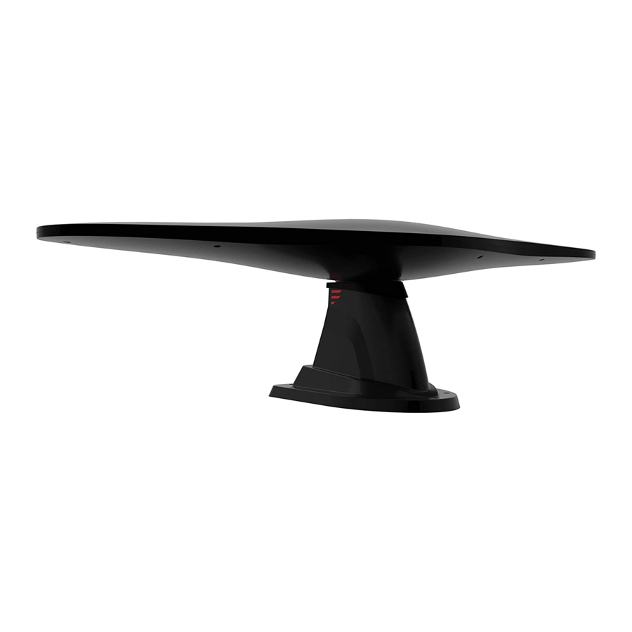
Product Overview Product Features ● Compatible with HDTV of various digital terrestrial signals (DVB-T, ISDB-T, DTMB, ATSC), stereo and FM/AM radios. ● The waterproof housing is UV resistant, and is designed for superior durability using injection mold. ● Omni directional antennas receive VHF, UHF, FM and AM signal from every point regardless of the direction you are traveling. -
Page 7: Installation
Installation Do not install couplers, splitters, etc. Making a New Opening between the power supply and the 1. Select a flat location where there is antenna. Installation of any item on sufficient area to mount and seal the the downlead may cause a short in the antenna to the roof surface. - Page 8 Installation 4. Thread the cables of the LTE antenna 6. Insert the bottom collar of the TV base through the opening. Put the antenna wing into the center hole of LTE antenna base over the opening the LTE antenna base. (Fig. 5) Make area.
- Page 9 Installation Rubber seal Collar Fig. 7 Fig. 8 9. Follow the wiring guidelines below to 4. Fix the TV antenna wing in the base connect the cables of TV/FM antenna using the two 4 x 12mm square (black) and FM/AM antenna (white) socket pan head tapping screws from the interior of the RV ceiling.
-
Page 10: Installing The Ceiling Mount Bracket
Installation with the cutting hole in the RV roof. Fig. 12 Fig. 10 Installing the Ceiling Mount 7. Fix the antenna base on the RV roof using seven stainless steel self- Bracket tapping screws and tighten using a screwdriver. (Fig. 11) **** NOTE: It is recommended that you NOTE: Do not overtighten as damage... -
Page 11: Mounting The Wall Plate
Installation − LTE Antennas: Connect to the 4. Place back the top cover to the ceiling rooftop unit by mapping the same mount bracket. (Fig. 16) wire color. − Power Wires: Connect to the RV +12Vdc (current rating >1A) power source. -
Page 12: Connections
Connections Wiring Diagram Refer to accessories page for planning connections. WARNING: The wall plate should be turned off while connecting cables. Connect the cables from the antenna to distribution wall plate and to the FM radio (AM Radio needs to connect the FM/AM antenna from the rooftop unit). Connect the power cables from the distribution wall plate according to the diagram below. -
Page 13: Operation
Operation Selecting TV Antenna Running a Channel Scan Reception To receive maximum number of channels, a channel scan is required To receive TV antenna reception, press once the antenna and power supply have the ON/OFF switch and the power been correctly installed and all cables indicator will be lit. -
Page 14: Specifications
Specifications Technical Specification FAN73B7C-BL2 MODEL FAN73B7C-BL FAN73B7C-BL3 OPERATING CONDITION VOLTAGE 9-16Vdc, 12Vdc typical CURRENT CONSUMPTION <100mA @ 12V AM/FM ANTENNA Frequency Range 520kHz to 1710kHz AM FUNCTION Radiation Direction Omni - direction Antenna Gain 15dB Max 10dB Max Max. output level 106dBμV... - Page 16 ● 52567 Independence Ct., Elkhart, IN 46514, USA ● Toll free: 1-800-789-3341 ● Email: support@furrion.com ©2007-2020 Furrion Ltd. Furrion and the Furrion logo are trademarks licensed for use by ® Furrion Ltd. and registered in the U.S. and other countries.
Need help?
Do you have a question about the FAN73B7C-BL and is the answer not in the manual?
Questions and answers