
Summary of Contents for Federal Pump BGP Series
- Page 1 •••••••••••••• •••••••••••••• •••••••••••••• •••••••••••••• •••••••••••••• i IMPORTANT READ ALL INSTRUCTIONS IN THIS MANUAL BEFORE OPERATING AND SERVING A PUMP...
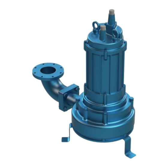
- Page 2 FRAME, COVER AND BASIN. (VALVING AND NOT INCLUDED) Sewage pumps provide for the lifting and Compatible with Federal Pump’s OS, FSS, SBS, disposal of sewage and sewage related fluids TCS, and NPC simplex, and duplex control from retaining basins or concrete pits and are...
-
Page 3: General Safety Information
Allow time for pumps to cool before handling or IMPORTANT!!! – Federal Pump is not responsible servicing the pump or any accessory items for losses, injury or death resulting from failure to associated with or near the pump. - Page 4 GENERAL SAFETY INFORMATION IWARNING: Do not use this pump in water over IMPORTANT!!! – Prior to installation, record 104˚F. exceed manufacturer’s Performance(GPM,TDH), Model Number, Record recommended maximum performance, as this Number, Full Load Amp, Voltage, Phase, and HP could cause the motor to overheat. from the pump name plate for future reference.
- Page 5 RECOMMENDATIONS RECEIVING: Immediately upon receipt of the VENT HOLE: The discharge piping of the pump shipment, inspect and check with the packing list should always be drilled with a vent hole(⅛”Ø) at and report to the transportation company’s local a height of 6” above the pump discharge to agent of any damage or shortage.
-
Page 6: Installation
INSTALLATION IWARNING: Under no circumstances should adequate working space. A minimum of 8” power or sensing cable be pulled while the pump diametrical clearance around the tank is is being transported or installed. Attach a chain or recommended. Never place basin directly in rope to the grip or lugging bolt to install the contact with rocks or other sharp objects. -
Page 7: Electrical Connections
INSTALLATION DISCHARGE PIPING: Discharge piping should be as becomes too high. (IMPORTANT!!! – The short as possible and sized no smaller than the overload panel should pump’s discharge size. Do not reduce the automatically reset and start the pump up discharge pipe size below that which is provided after the motor cools.) In the event of an on the pump. - Page 8 INSTALLATION LIQUID LEVEL CONTROL (1Ph/230V & 3Ph): Refer to the figure 1 which shows a typical installation of (2) 1 phase 230 volt and 3 Phase pump at all voltage using (3) level control switches (SW1, SW2, SW3) and (1) high water alarm switch (SW4) mounted to the style 1 pilot device with a duplex control panel.
-
Page 9: Operation
OPERATION PRE-OPERATION: After completing installation, Since Federal Pump offers a multitude of liquid perform the following prior to contacting Federal level controls, please refer to their (OS, FSS, SBS, Pump’s local representative for equipment start TCS, NPC) corresponding IOM manual for sequence of operation 1. - Page 10 NOTE: Federal Pump assumes no responsibility for damage or injury due to disassembly in the field. Disassembly of the pumps or supplied accessories other than at Federal Pump or its authorized service centers, automatically void warranty on the equipment...
-
Page 11: Maintenance
MAINTENANCE INSPECTION: Schedule to check pressure, output, sure it is clean and clear (light amber in color voltage, current, and other specifications on a bi- and free from suspended particles). Milky annual basis. If unusual readings are found, and white oil indicates the presence of water. Oil correct as soon as possible. - Page 12 MAINTENANCE PRESSURE TEST (IF OIL HAS BEEN DRAINED): PRESSURE TEST (AIR FILL MOTOR) Remove pipe plug from housing. Apply pipe Remove pipe plug from housing. Apply pipe sealant to pressure gauge assembly and tighten sealant to pressure gauge assembly and tighten into hole.
-
Page 13: Mechanical Seal
MAINTENANCE DISASSEMBLY: When disassembling pump, have a leads and remove motor housing and piece of cardboard or wooden board ready to O-ring. Always replace O-ring and place the different parts on as you work. Do not gasket once removed. pile parts on top of each other. They should be f) For single phase motors, check motor laid out neatly in rows. - Page 14 MAINTENANCE ASSEMBLY: All parts must be clean before reassembly. Handle seal parts with extreme care. DO NOT damage lapped surfaces. Reassemble in reverse order of disassembly. Be careful of the following: 1. During reassembly, periodically. rotate the impeller by hand and check for smooth rotation.
- Page 15 NOTES ••••••••••••••...
- Page 16 Federal Pump Corporation Factory Warranty Equipment or parts manufactured by Federal Pump Corporation (“Seller”) which fail to function properly because of defects in material or workmanship and which are returned to Seller with shipping charges prepaid, within one year from date of shipment (invoice date) will be repaired or replaced by Seller, FOB the factory, at Seller’s expense.
Need help?
Do you have a question about the BGP Series and is the answer not in the manual?
Questions and answers