Table of Contents
Advertisement
Available languages
Available languages
Quick Links
Advertisement
Table of Contents

Summary of Contents for Funkwerk plettac VNS 102V2
- Page 1 (D) Bedienungs-/Montageanleitung (GB) Operation / Installation Manual VNS 102V2 Funkwerk plettac electronic GmbH Würzburger Str. 150 D 90766 Fürth Tel.: 0911/75884-0 43522-941.96(00) Fax: 0911/75884-100 Änderungen vorbehalten/Subject to change without notice 11/2009...
-
Page 2: Table Of Contents
Inhaltsverzeichnis / table of contents (D) Deutsch Allgemeine Beschreibung Wartung Hilfe bei Störungen Lieferumfang: Entsorgung Steckerbelegungen VNS 102V2 Spannungsversorgung des VNS 102V2 LAN-Schnittstelle Serielle RS485 Schnittstelle Audio Digitale I/O Zubehör für VNS 102V2 Inbetriebnahme / Konfiguration Auslieferzustand: Notwendiges Zubehör zur Erstinbetriebnahme / Konfiguration Inbetriebnahme und Konfiguration des VNS 102V2 Technische Daten Maßbild VNS 102V2... - Page 3 Alle Einstellvorgänge bei Inbetriebnahme und Service werden überwiegend über die Steuerschnittstelle bzw. die Web-Seite, aber immer bei geschlossenem Gerät ausgeführt. Das Gerät darf nur im Werk durch geschulte und autorisierte Personen geöffnet werden, da sonst auch mit Langzeitbeschädigungen und Ausfall des Kühlsystems zu rechnen ist! Bei Schäden durch Nichtbeachten der Bedienungsanleitung oder Öffnen des Geräts erlischt der Garantieanspruch.
-
Page 4: Allgemeine Beschreibung
Netzlast erheblich bessere Bildqualität bei dynamischen Bildsequenzen. Das ist für Übertragung und Aufzeichnung ein sehr wichtiger Vorteil. Die Konfiguration kann über Webbrowser (HTML) und Funkwerk plettac Managementsystem p.o.s.a. erfolgen. Bei Auftreten von Alarmen können MPEG-4 Sequenzen konfigurierbar in Länge (auch Vorgeschichte), Bildrate und Bildqualität im lokalen Speicher aufgezeichnet werden. -
Page 5: Lieferumfang
Lieferumfang: • VNS 102V2-Codec (19“ Einbaukassette) Best.-Nr. 943522190600 • CD mit ausführlicher Dokumentation und Streaming Plugin SW • 2 Jumper • Bedienungs- und Montageanleitung Best.-Nr. 435229419600 Entsorgung Entsorgen Sie das Gerät entsprechend den geltenden gesetzlichen Vorschriften. VNS 102V2 11/2009... -
Page 6: Steckerbelegungen Vns 102V2
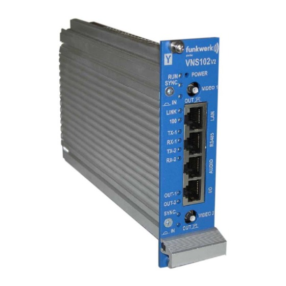
Steckerbelegungen VNS 102V2 RJ 45 „Audio“ RJ 45 „Audio“ RJ 45 „I/O“ „I/O“ RJ 45 4-poliger DIP-SWITCH 1 2 3 4 VNS 102V2 11/2009... -
Page 7: Spannungsversorgung Des Vns 102V2
Spannungsversorgung des VNS 102V2 Die Spannungsversorgung erfolgt über den Powerstecker: auf der Rückseite des VNS 102V2. Signal WAGO Stecker Pin Beschreibung - Pol (Ground) + Pol (Power min. 9,5 bis max. 32 VDC) FRAME Chassis Ground Empfohlenes Netzteil für Einbau in 19“ Baugruppenträger: TM11 (siehe Zubehör) VNS 102V2 11/2009... -
Page 8: Lan-Schnittstelle
LAN-Schnittstelle Die LAN Schnittstelle entspricht dem Standard IEEE802.1 mit 10/100Mbit (autosense) über Cat-5 Kabel (10/100BaseT). Als LAN-Anschluss steht ein RJ45 Stecker an der Frontseite des VNS 102V2 mit der Bezeichnung „LAN“ zur Verfügung. Signal RJ45 “LAN” Signal RJ45 “LAN” VNS 102V2 11/2009... -
Page 9: Serielle Rs485 Schnittstelle
Serielle RS485 Schnittstelle Der Anschluss beider Schnittstellenports erfolgt über einen RJ45 Stecker an der Frontseite des VNS 102V2 mit der Bezeichnung „RS485“ RS485” RS485” TX+ COM 1 (UART A) TX- COM 1 (UART A) RX+ COM 1 (UART A) TX+ COM 2 (UART B) TX- COM 2 (UART B) RX- COM 1 (UART A) RX+ COM 2 (UART B) -
Page 10: Audio
Audio Als Ein- und Ausgangsstecker für das analoge Audiosignal wird ein RJ45 Stecker an der Frontseite des VNS 102V2 mit der Bezeichnung „AUDIO“ verwendet. Signal (In) RJ45 „AUDIO“ Beschreibung R_IN Line In - rechter Kanal Signal AGND_AUDIO_IN1 Line In - rechter Kanal GND L_IN Line In - linker Kanal Signal AGND_AUDIO_IN2... -
Page 11: Digitale I/O
Digitale I/O Der Anschluss beider digitalen Ein- bzw. Ausgänge erfolgt über den RJ45 Stecker an der Frontseite des VNS 102V2 mit der Bezeichnung „I/O“ Signal RJ45 “I/O” Signal RJ45 I/O OUT1+ (Ausgang 1, Signal) OUT1- (Ausgang 2, GND) IN1+ (Eingang 1, Signal) OUT2+ (Ausgang 2, Signal) OUT2- (Ausgang 2, GND) IN1- (Eingang 1, GND) -
Page 12: Zubehör Für Vns 102V2
Zubehör für VNS 102V2 19“ Baugruppenträger kpl. verdrahtet incl. Netzkabel und 2 Blindplatten Best.-Nr. 943525150100 Trafomodul TM11 Best.-Nr. 943435120300 Blindplatten (7 TE blau) Best.-Nr. 943525180700 Rüstsatz Kabel Best.-Nr. 943525160100 Rüstsatz Anschlußeinheit Best.-Nr. 943522190500 Rüstsatz AK 187 Best.-Nr. 943525150500 CD mit Active X (Software zur Darstellung eines Videobildes auf dem PC-Monitor) Best.-Nr. - Page 13 • Der Verbindungsaufbau PC/VNS 102V2 erfolgt mit Hilfe eines auf dem PC installierten Internetbrowsers. • Bevor Sie die IP-Adresse des VNS 102V2 ändern können, muß über den Internetbrowser eine Verbindung mit dem VNS 102V2 über die derzeitige IP-Adresse des VNS 102V2 bestehen; bei einem neuem Gerät ist dies die Default-IP-Adresse 192.168.128.2.
- Page 14 Internetexplorer aufrufen! Unter Extras Internetoptionen Verbindungen Einstellungen finden Sie das folgende Fenster: Falls ein Proxy-Server verwendet wird, muss dieser für lokale Adressen umgangen werden. Homepage des VNS 102V2 anwählen und IP-Adresse des VNS 102V2-Encoders / VNS 102V2- Decoders einstellen: Hinweis: Falls sich nach dem Ändern von IP-Adressen, mit dem Browser keine Verbindung mehr herstellen läßt, kann ein Löschen der ARP-Einträge durch Eingabe von „arp –d“...
- Page 15 IP-Adresse wie gewünscht einstellen (z.B. 192.168.128.10 für den Encoder 192.168.128.11 für den Decoder) anschließend mit „Store & apply“ im VNS 102V2 speichern. Hinweis: Die Verbindung zwischen Explorer und VNS 102V2 ist bei Änderung der IP- Adresse unterbrochen, eine erneute Verbindung muss mit der neu eingestellten IP-Adresse über den Explorer erfolgen.
- Page 16 Einstellungen im Fenster „Transfer“ für den Encoder Aktivierung der „Sende-Instanzen“ beim Encoder: Instance 1: „aktive“ markieren und mit „Apply“ bestätigen. Instance 2: „aktive“ markieren und mit „Apply“ bestätigen. Der VNS 102V2-Encoder ist jetzt so konfiguriert, dass zwei Videosignale „gestreamt“ werden, wenn an beiden Videoeingängen ein normgerechtes Videosignal anliegt! VNS 102V2 11/2009...
- Page 17 Spezielle Konfiguration der „Decoder-Ausführung“ Einstellungen im Fenster „Transfer“ für den Decoder Aktivierung der „Empfänger Instanzen“ beim Decoder: Receive Video output 1: „aktive“ markieren und mit „Apply“ bestätigen. Receive Video output 2: „aktive“ markieren und mit „Apply“ bestätigen. Der VNS 102V2-Decoder ist jetzt so konfiguriert dass zwei Videosignale „empfangen“ werden! Wenn Sie nun Encoder und Decoder mit einem „Crossover-Kabel“...
-
Page 18: Technische Daten
Technische Daten Prozessor TI DSP TMS320 DM642-720MHz Video Input 2 FBAS Eingänge Eingangsimpedanz 75 Ω Auto Gain -3 dB bis +6 dB Video Output 2 FBAS Ausgänge, 75 Ω Videoformat PAL, NTSC Bildrate Full Frame Interlaced 50-/60-fields/s, Full Frame oder Half Frame von 0,1fps bis zu 30 fps/Kanal Sampling Rate ITU-R BT.601... -
Page 20: (Gb) English
(GB) English All adjustments during commissioning and servicing are mainly performed via the control interface and/or the website, but always while the device is closed. The device may only be opened in the factory by trained and authorised personnel to prevent long- term damage and failure of the cooling system! The warranty will be void in case of damage caused by non-compliance with the operating instructions or opening the device. -
Page 21: General Description
This is a very important advantage for transmission and recording. The device can be configured via a web browser (HTML) and the Funkwerk plettac management system p.o.s.a. In case of alarms, MPEG-4 sequences can be recorded in the local memory. The length (also previous history), frame rate and image quality can be configured. -
Page 22: Delivery Scope
Delivery scope: • VNS 102V2 codec (19" built-in cassette) Order no. 943522190600 • CD with detailed documentation and streaming plugin SW • 2 jumpers • Operating and installation manual Order no. 435229419600 Disposal Dispose of the device in line with the valid legal regulations. VNS 102V2 11/2009... -
Page 23: Pin Assignment Vns 102V2
Pin assignment VNS 102V2 RJ 45 „Audio“ RJ 45 „I/O“ 4 Pin DIP-SWITCH 1 2 3 4 VNS 102V2 11/2009... -
Page 24: Voltage Supply Of The Vns 102V2
Voltage supply of the VNS 102V2 Voltage supply via the power plug: on the rear of the VNS 102V2. Signal WAGO plug pin Description - pole (ground) + pole (power min. 9.5 up to max. 32 VDC) FRAME Chassis ground Recommended power supply unit for installation into 19"... -
Page 25: Lan Interface
LAN interface The LAN interface corresponds to the standard IEEE802.1 with 10/100Mbit (autosense) via cat-5 cable (10/100BaseT). An RJ45 connector is located on the front of the VNS 102V2 for LAN connection (labelled "LAN"). Signal RJ45 "LAN" Signal RJ45 "LAN" VNS 102V2 11/2009... -
Page 26: Serial Rs485 Interface
Serial RS485 interface Both interface ports are connected via an RJ45 plug on the front of the VNS 102V2 (labelled "RS485"). RS485" RS485" TX+ COM 1 (UART A) TX- COM 1 (UART A) RX+ COM 1 (UART A) TX+ COM 2 (UART B) TX- COM 2 (UART B) RX- COM 1 (UART A) RX+ COM 2 (UART B) -
Page 27: Audio
Audio An RJ45 plug is used on the front side of the VSN 102V2 (labelled "AUDIO" as input/output plug for the analog audio signal. Signal (In) RJ45 "AUDIO" Description R_IN Line In - right channel signal AGND_AUDIO_IN1 Line In - right channel GND L_IN Line In - left channel signal AGND_AUDIO_IN2... -
Page 28: Digital I/O
Digital I/O Both digital inputs/outputs are connected via the RJ45 plug on the front of the VNS 102V2 (labelled "I/O"). Signal RJ45 "I/O" Signal RJ45 I/O OUT1+ (output 1, signal) OUT1- (output 2, GND) IN1+ (input 1, signal) OUT2+ (output 2, signal) OUT2- (output 2, GND) IN1- (input 1, GND) IN2+ (input 2, signal) -
Page 29: Accessories For The Vns 102V2
Accessories for the VNS 102V2 19" sub-rack, compl. wired incl. mains cable and 2 dummy boards Order no. 943525150100 Transformer module TM11 Order no. 943435120300 Dummy boards (7 TE blue) Order no. 943525180700 Set of cables Order no. 943525160100 Mounting kit connection unit Order no. - Page 30 the chapter "Delivery status". In the description further down, we will use the default address of the VNS 102V2. Notice: Establishing a connection between the PC and the VNS 102V2 is only possible if the network settings of the PC coincide with the class of the IP address and the used subnet mask of the VNS 102V2. With all further settings, we assume that you are using a PC with Windows XP.
- Page 31 Start the Internet Explorer! In Tools Internet options Connections Settings, you will see the following window: If you are using a proxy server, this must be circumvented for local addresses. Addressing the homepage of the VNS 102V2 and setting the IP address of the VNS 102V2 encoder/VNS 102V2 decoder: Notice: If it is no longer possible to establish a connection with the browser after changing IP addresses, deleting the...
- Page 32 Set the IP address as desired (e.g. 192.168.128.10 for the encoder 192.168.128.11 for the decoder), then save with "store & apply" in the VNS 102V. Notice: When changing the IP address, the connection between the Explorer and the VNS 102V2 is interrupted; a new connection must be established via the Explorer with the newly set IP address.
- Page 33 Settings in the window "Transfer" for the encoder Activation of the "send instances" on the encoder: Instance 1: „Mark "active" and confirm with "apply". Instance 2: „Mark "active" and confirm with "apply". Now the VNS 102V2 encoder is configured in such a way that two video signals are streamed if a standard video signal is applied to both video inputs.
- Page 34 Special configuration of the "decoder" model Settings in the window "Transfer" for the decoder Activation of the "receive instances" on the decoder: Receive video output 1: „Mark "active" and confirm with "apply". Receive video output 2: „Mark "active" and confirm with "apply". Now the VNS 102V2 decoder is configured to receive two video signals.
-
Page 35: Technical Data
Technical data Processor TI DSP TMS320 DM642-720MHz Video input 2 FBAS inputs Input impedance 75 Ω Auto gain -3 dB to +6 dB Video output 2 FBAS outputs, 75 Ω Video format PAL, NTSC Frame rate Full frame interlaced 50-/60 fields/s, full frame or half frame from 0.1fps to 30 fps/channel Sampling rate ITU-R BT.601...
Need help?
Do you have a question about the plettac VNS 102V2 and is the answer not in the manual?
Questions and answers