Table of Contents
Advertisement
Advertisement
Table of Contents
Troubleshooting

Summary of Contents for caron 7310-22
- Page 2 At Caron, we are committed to continuous quality improvement. Our goal is to supply our customers with highly reliable equipment at a fair price. In order to openly monitor our performance, we would appreciate your feedback on our products and services.
- Page 3 Revision Log Version Date Description Rev A 07-20-18 Initial release Added analog output adjustable temperature Rev B 05-14-19 range feature. Rev C 06-06-19 Added 7315 light sensor location info. Rev D 09-18-19 Updated Replacement Parts List Rev E 11-19-19 Added Appendix on Dehumidification 7310 Series Operations Manual REV E 11-19-19 Page 3 of 131...
-
Page 4: Table Of Contents
TABLE OF CONTENTS Warranty ......................6 Equipment Overview ..................9 Installation ....................12 Unpacking Choosing a Location Preliminary Cleaning Installing the Port Stoppers Installing the Shelves Leveling the Unit Connecting the Drain Line Connecting Electrical Power Connecting the Led Lighting Optional Accessory Installation .............. - Page 5 Calibration ....................80 The Calibration Screen Calibrating the Temperature Calibrating the Humidity Calibrating the CO Calibrating the Lights Calibrating Optional Chart Recorders Alarms ......................87 Alarm System Overview Snoozing the Speaker Muting the Speaker Changing Alarm Setpoints Alerts ......................94 Alert System Overview Resetting the Maintenance Screen Info .......................
-
Page 6: Warranty
Parts and labor for a period of one (1) year from date of shipment. • Any part found defective will be either repaired or replaced at Caron’s discretion, free of charge, by Caron in Marietta, OH. Parts that are replaced will become the property of Caron. - Page 7 Force Majeure or Acts of God. This writing is a final and complete integration of the agreement between Caron and the customer. Caron makes no other warranties, express or implied, of merchantability, fitness for a particular purpose or otherwise, with respect to the goods sold under this agreement.
- Page 8 INTERNATIONAL SYMBOLS AND DEFINITIONS Help Information Warning of hazardous area Warning of hot surface Warning of dangerous electric voltage Earth (ground) protective conductor WARNINGS Local government may require proper disposal 7310 Series Operations Manual REV E 11-19-19 Page 8 of 131...
-
Page 9: Equipment Overview
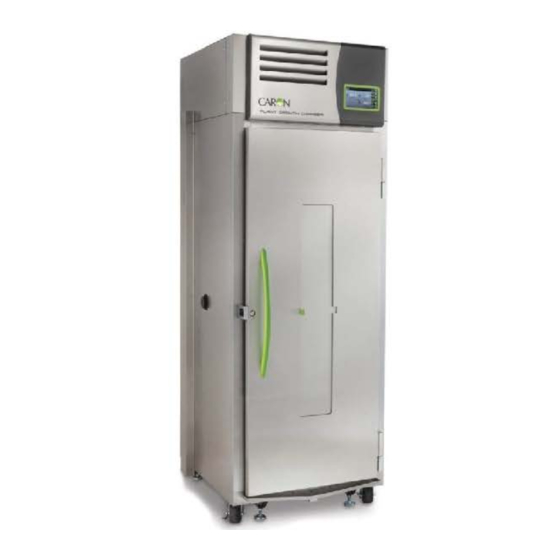
7” Full Color HMI Replaceable air intake filter, behind bezel Power Switch Solid Door Illuminated standard Caron Logo (DOOR315 option shown) LED Light Bank(s) Right Side Access Port Left Side Access Port Temperature (optional Humidity,... - Page 10 EQUIPMENT OVERVIEW – CONTINUED Status Bar Actual Day / Time Temperature Setpoint Speaker Menu Lockout Settings icon Menu Trend Parameter Graph Display Zones Light Cycle Menu Actual Light Current (Home Screen) screen indicator Navigation Pane (indicates menu depth) Submenu categories (Settings Screen) 7310 Series Operations Manual REV E 11-19-19...
- Page 11 LED Light Banks The standard units come with white LED lights. If one of the optional light configurations is purchased, it may contain a combination of the 4 colors: red, white, blue and far red (infra-red) Far-red LED light for plant growth is much dimmer than the rest. The human eye can only see to about 700 nm and the far red peaks in the 720-740 nm LED.
-
Page 12: Installation
Choose a location where these facilities are, or can be made available. If a water source or a drain is not available, contact Caron customer service and ask about our CRYS102 product line or click this web link for information on the product: www.caronproducts.com... -
Page 13: Preliminary Cleaning
Prior to installation, take time to consider what the height of the product being placed in the chamber will be and set the shelf spacing accordingly. Additional shelving can be purchased through Caron customer service if necessary. The chamber should be empty when being moved. -
Page 14: Leveling The Unit
Do not have multiple loaded shelves out simultaneously or the chamber may tip. Leveling the Unit Place a level on the middle shelf of the incubator. Adjust the feet until the unit sits level left to right and front to back. Even if the unit is level without adjustment, the leveling feet should still be lowered to avoid the cabinet moving while opening and closing the outer door &... - Page 15 Kinks or elevations in the drain line above the cabinet drain will not allow the chamber to drain. If a local floor drain is not available, a variety of accessories are available through Caron customer service. These accessories can also be viewed at www.caronproducts.com.
-
Page 16: Connecting Electrical Power
Connecting Electrical Power Connect each chamber to a grounded circuit. Failure to do so could result in electrical shock. The unit requires a dedicated electrical outlet. See table below for model specific power required and connection. This covers 7310,7311,7312,7315 and 7317 model numbers. Model # Power Requirements Plug Connection... -
Page 17: Connecting The Led Lighting
Connecting the Led Lighting Plant Growth Chambers with LED lighting have light banks consisting of 2, 9 or 24 LED clusters on each bank. The LED banks are suspended under each shelf. The light banks are shipped fully installed in place and wired from the factory. See the Operations or Maintenance sections of the manual for more details. -
Page 18: Optional Accessory Installation
OPTIONAL ACCESSORY INSTALLATION Connecting Alarm Contacts (ALRM302) With the purchase of ALRM302, a set of terminals on the rear of the unit is provided to monitor Temperature, Lights, Humidity (optional), CO (optional) alarms. With the alarm contacts, the terminals provided allow for a NO (normally open) output, a NC (normally closed) and COM (common) connection. -
Page 19: Connecting The Co 2 Supply (Co2C302)
15-20 psi. CO tank regulators can be purchased through Caron customer service. Once the cylinder regulator is installed, connect the outlet of the regulator to the hose barb fitting using the tubing and clamps provided. An inline HEPA filter is provided to remove any contaminants in the CO gas supply. - Page 20 To ensure proper operation, distilled or deionized water is required as a supply on units that have humidity control. If these water sources are not available contact Caron customer service. Use only distilled or deionized water with a resistivity between 50KΩ-CM and 1MΩ-CM and...
- Page 21 A water inlet fitting on the back of the unit and ¼” black tubing are provided to connect the water supply to the chamber. Connect an appropriate water supply to the fitting. Incoming line pressure should be regulated to not exceed 80 psi. If a Condensate Recirculator water recycling system was purchased as a water supply, refer to its user’s manual for proper installation.
- Page 22 Connecting Analog Outputs (OUTP302, OUTP303 & OUTP304) With the purchase of OUTP302, OUTP303, OUTP304, OUTP307, OUTP308 the controls are equipped with analog outputs. A set of terminals are provided on the back of the unit to connect to the analog outputs. Analog Output Connections Analog outputs provide either a milliamp (4-20mA) or voltage (0-5V) signal output to...
- Page 23 Parameter Voltage Current Corresponding Value Temperature 0 – 5 V 4-20 mA -50 – 100 °C (adjustable*) Lights 0 – 5 V 4-20 mA 150 – 1500 µmoles/m2/s Humidity 0 – 5 V 4-20 mA 0 – 100 %RH 0 – 5 V 4-20 mA 0 –...
-
Page 24: Installing Drain Water Pump (Pump301)
Internal Level Switch In applications where a floor drain is not available and a Caron water recycling system is not being used, a drain pump can be purchased to pump any excess condensate from the chamber to a local sink or drain. The pump is located near the middle of the back of the chamber. -
Page 25: Operation
OPERATION Before the unit can be commissioned for use, make sure that the following steps have been completed: - Chamber is properly installed and level. - The appropriate utilities connected to the chamber. With the above mentioned steps complete, the power switch located on the right side, near the top of the unit exterior, can be turned on. - Page 26 Using the Keypad This control system uses a numeric keypad to enter all parameter values. Similar to a calculator, this allows quick and precise entry of values. When any numeric value button is pressed, the keypad display will pop up over the current display. Parameter Description Range of variable Header...
- Page 27 : By pressing the Screen Saver button “on” this will automatically enter screen saver mode after 15 minutes. At this time, the screen will be completely blank (ie. black). The illuminated Caron logo (see Equipment Overview section) shows that the unit is powered on and functioning.
- Page 28 Controlling LED Lighting The plant growth chamber comes with a Diurnal lighting system used to simulate day and night conditions. The 24 hour cycle that can be programmed with separate temperature and humidity (optional) setpoints that correspond with the “day” (lights on) and “night”...
- Page 29 Using Light Cycle Features Light Cycle Timer Setup Active Light Start / Stop Banks Timer Continuous Light The Light Cycle screen has parameters that can be set up for various conditions. Hour Minute AM or PM Lights On Start Time Lights Off End Time Gradual Light...
- Page 30 Light Bank On/ Off The Active Light Banks (button) lets you choose which light banks you want “on” or “off” during the light cycle. This feature can also be used when the light cycle is setup for Continuous Light and the light timer is not required. (Not available on all models) 7310 Series Operations Manual REV E 11-19-19...
- Page 31 Start / Stop Timer When the Start / Stop Timer (button) is active, the light timer will run the cycle based on the parameters that were set up. An icon appears in the status bar letting the user know that the Light Cycle is running (during this cycle the Continuous Light feature is disabled).
- Page 32 Setting the Light Cycle Timer Light Cycle Menu Screen shown with optional humidity To set the Light Cycle Timer, press the (Light Cycle) button on the right side the screen. press the (Timer Setup) button on the left side of the screen. 7310 Series Operations Manual REV E 11-19-19 Page 32 of 131...
- Page 33 Minutes Hour AM or PM Lights On Start Time Lights Off End Time Gradual Light Press the Lights On Start Time hour button and the enter the hour that you want the lights to come on. Finish by pressing (Ent) key. Then press the “minutes”...
- Page 34 Select Gradual Light button to simulate sunrise and sunset light conditions. (optional) Go back to the previous screen by pressing (Light Cycle) button. From this screen press the Active Light Banks (button). This feature is only available on chambers with multiple independent light banks, and screen appearance will vary depending on set up.
- Page 35 Go back to the previous screen by pressing (Light Cycle) button. To activate the Light Cycle Timer press the Start / Stop Timer button. 7310 Series Operations Manual REV E 11-19-19 Page 35 of 131...
- Page 36 Light Cycle Status The Light Cycle is programmed to automatically change lights, temperature and humidity (optional) over a 24 hour period. The Light Cycle Info screen is intended to provide a comprehensive visual illustration of the Light Cycle settings and current conditions. When the Light Cycle is on, the status of the cycle time can be displayed by pressing the Light Cycle icon that is in the Status Bar.
- Page 37 Current ‘Day’ start time time ‘Night’ set ‘Day’ set points points Light bank ‘Night’ status start time When Light Cycle is active the Light Cycle Info icon appears in the Status Bar. Press this icon button and Light Cycle Info screen will appear displaying information about the Light Cycle including current time.
- Page 38 7315-22 Light Sensor Location The light sensor on models 7315-22 Tissue Culture have a specific location on the duct sheet of the chamber. Light intensities were tested with the light sensor at this location which is for normal operations of the chamber. If the light sensor needs to be moved for other tests, this “home”...
- Page 39 Changing the Temperature Setpoint The steps below walk through an example of changing the temperature setpoint from 30.0 °C to 20.0 °C. This example shows (optional) humidity control and CO . Here is the Home Screen display. Setpoint Button Actual Temperature To set the temperature setpoint, press the (Setpoint) button on the right...
- Page 40 Temperature Setpoint Daytime Temperature Setpoint Nighttime Press the (Temperature Setpoint) button. (In this example the temperature setpoint initially has a value of ’30.0’; this will vary with different initial setpoint values.) Keypad A temperature setpoint window will appear. Enter the temperature setpoint by using the keypad.
- Page 41 Changing the Light Setpoint The steps below walk through an example of changing the light setpoint to 600 µmol/m2s. This example shows (optional) humidity control and CO . Here is the Home Screen display. Setpoint Button Actual Light To set the light setpoint, press the (Setpoint) button on the right side of the screen.
- Page 42 Keypad Enter the new light setpoint on the keypad as desired and press (Enter) when complete. Press the (Home) button to return to the main screen. 7310 Series Operations Manual REV E 11-19-19 Page 42 of 131...
- Page 43 If light bank setpoint is set too low beyond the low range of the LED lights, this low level dimming value is approximately (10%-15%), the lights will stay on at the minimum dimming level. The info button will appear in the Status Bar. Info button This Info pop up window is informing the user that the setpoint value that has been entered exceeds the lowest amount of light that the lights can be dimmed.
- Page 44 Changing the Humidity Setpoint (HUMD312, HUMD313 & HUMD314 only) The steps below walk through an example of changing the humidity setpoint. Here is the Home Screen display. Setpoint Button Actual Humidity Press the (Setpoint) button on the right side of the screen. Humidity Setpoint Button To set the humidity setpoint, press the...
- Page 45 Keypad Enter the new humidity setpoint on the keypad as desired and press (Enter) when complete. Home Button Press the (Home) button to return to the main screen. 7310 Series Operations Manual REV E 11-19-19 Page 45 of 131...
- Page 46 Changing the CO Setpoint (CO2C302) The steps below walk through an example of changing the CO setpoint. Here is the Home Screen display. Setpoint Button Actual Press the (Setpoint) button on the right side of the screen. CO2 Setpoint Button To set the CO setpoint, press the (CO2) button.
- Page 47 Keypad Enter the new CO setpoint on the keypad as desired and press (Enter) when complete. Press the (Home) button to return to the main screen. 7310 Series Operations Manual REV E 11-19-19 Page 47 of 131...
-
Page 48: Optional Accessory Operation
Continuous writing to the flash drive necessitates a high quality industrial grade device. Use only the flash drive provided by Caron (or equivalent: single level cell memory, wear leveling algorithms, error correcting code). File name format is “DATE START YYYY-MM-DDTHH-MM_.csv” (hours in 24 hour time) When the chamber is on, the chamber’s history data is being stored even when a flash... - Page 49 Here are the methods for retrieving data: Continuous logging of data Insert the flash drive into the chamber’s USB port. When first inserted, it creates a .csv file called ‘DATA START’ with the current date and time in the file name. At 5 min intervals, the chamber’s process values are appended to the file.
- Page 50 All Data There is also an ‘All Data’ feature to indicate if the upload should include all data (since the unit has been used) or just the history data since a flash drive was last inserted. An ‘Info’ button will appear in the status bar warning the user not to remove the flash drive while the data is being uploaded.
- Page 51 Setup Button Press the (Setup) button. USB Button Press the (USB) button. When the ‘Auto Export’ button is selected this will retrieve the data starting at the point of the last download, and continuing to the present time. 7310 Series Operations Manual REV E 11-19-19 Page 51 of 131...
- Page 52 When the ‘All Data’ button is selected this will retrieve data starting at the point of the last download, and continuing to the present time. USB flash drive icon Info button Eject button When flash drive is inserted into the USB port a ‘USB flash drive’ icon and flashing ‘Info’ button appears in the status bar indicating that the data is being downloaded to the flash drive.
- Page 53 Operation of the Viewing Window (DOOR315, DOOR316, DOOR317) All models of 7310 series -22 -50 -75 can all have their solid doors replaced with the feature of an optional viewing window. This option allows the samples to be viewed without opening the door and disturbing the temperature, lights, humidity and CO control.
- Page 54 Operation of Variable Color Light Control (LGHT331 thru LGHT339) The optional Variable Color Light Control feature allows independent lighting control of up to four different light colors: White, Blue, Red and Far Red. The relative light intensity of these can vary per light bank or chamber section. Independent lighting control works by using the same ‘overall’...
- Page 55 Condition: Low Light Ratio - If the Light Ratios are set at 5% white,5% blue,5% red 100% far red, it would be expected that a Light Intensity Setpoint of 600 umoles/m2/s would not be attainable with light from predominantly far-red lighting. - If the Light Ratios are set at: 100% white,1% blue,100% red 100% far red, it would be expected that blue’s setting of 1% would encounter the minimum dimming level situation.
- Page 56 Light Cycle Menu Screen shown with optional humidity To set the Light Cycle, press the (Light Cycle) button on the right side of the screen. Ratio Menu The Ratio Menu (button) allows the user to change each color ratio of a light bank (optional feature).
- Page 57 Selecting the Top Bank (button) will open a screen where you can adjust the intensity of each of the 4 colors of LED clusters. Light Intensity Ratio % Press one of the 4 color Intensity Ratio Entry buttons 7310 Series Operations Manual REV E 11-19-19 Page 57 of 131...
- Page 58 Enter value using keypad, finish by pressing (Ent) key. Repeat for other color intensities. Press Ratio Menu button to change other light banks. After programming the specified setpoints and settings, the lighting will adjust according to the specified Light Intensity Setpoint. After 15 mins have passed, if there is no alarm on the screen then the Light Intensity Setpoints and Light Ratio values are within an acceptable range.
- Page 59 Below are examples of Light Intensity Setpoints and the results when Light Ratio values are set at 100% and output values other than 100%. Example 1 shows the Light Intensity Setpoint set to 600 umoles/m2/s. All 4 colored light ratios are set to 100%. Light Light Intensity...
- Page 60 Example 3 will alarm due to the Light Ratio values are set too high for a Light Intensity Setpoint of a lower value. Example 4 shows the Light Intensity Setpoint set to 200 umoles/m2/s. White 0%, Blue 28%, Red 50%, Far Red 15%. Example 4 Example 5 shows the Light Intensity Setpoint set to 600 umoles/m2/s.
- Page 61 Example 7 shows the Light Intensity Setpoint set to 50 umoles/m2/s. White 0%, Blue 50%, Red 100%, Far Red 25%. Example 7 7310 Series Operations Manual REV E 11-19-19 Page 61 of 131...
-
Page 62: Door Light Interior Viewing White Light (Lght331 Thru Lght339)
Door Light Interior Viewing White Light (only with LGHT331 thru LGHT339) Raising plants can be difficult to see whether plants are growing properly without the full color spectrum. This feature allows the customer to temporarily see inside the chamber with full spectrum lighting (regardless of setting: white lights on, colored lights off). There is a manual mode controlled by the HMI (when the customer uses the viewing window) and automatic mode (when customer uses the full door and light change is activated by a door switch. -
Page 63: Operation Of The Ramp / Soak Control (Ramp301)
Operation of Ramp/Soak Control (RAMP301) A ramp and soak control system allows the user to store up to 50 steps spanning 5 profiles. A step consists of a change in setpoint (ramp), or maintain a setpoint for a fixed duration (soak). A step(s) can be repeated any number of times from 1 to 0 255 or infinite (repeat). - Page 64 Profile Step buttons Current Profile Continue to Profile button Press the (Step 1) button. Repeat button Ramp button Current Step Unused button Soak button Press the (Ramp) button. Parameters that can change for profile Step type Ramp Rate parameters To set the ramp temperature value, press the (Temperature) button.
- Page 65 Ramp rate allows a user to control the rate which parameters (temperature, humidity, CO , lights) change when transitioning to a new setpoint. This allows for a more gradual change than otherwise would occur. Temperature tolerance range is 1°C when ramping temperature. Humidity tolerance is 2% when ramping humidity.
- Page 66 Wait for Process When (Wait for Process) button is selected, the parameter step will wait until the setpoints have been reached before proceeding to the next step. Press the (Profile 1) button to go back to the Profile 1 screen to set up Step 2.
- Page 67 Press the Soak) button. Press (Hours) and or (Mins) button(s) for desired soak time. This feature allows the unit to stay at the Ramp value for a specified amount of time before going to the next Step. Enter values, example 2 hrs-10 mins. When finished entering values, press the (Profile 1) button to go back to the Profile 1 screen to set up Step 3.
- Page 68 Press (Step 3) button, Choose the (Repeat) button. To enter which step is to be repeated press the and enter value on pop up key pad. There is a note that gives specific instructions which steps can be repeated. After entering the specified step, the number of repeats for that step can be specified.
- Page 69 Enter values, example 2 for Step and 10 for # Repeats. Once this is complete press the (Profile 1) button to return to the Profile 1 screen. Press (Step 4) button. 7310 Series Operations Manual REV E 11-19-19 Page 69 of 131...
- Page 70 Choose the Unused button. The Unused step is set up to be the “default” condition. So when the Ramp, Soak or Repeat condition is not chosen for a step, the ramp profile program will skip over those unused steps. When all of the Ramp profiles are entered, press the Start / Stop button and the ramp cycle program will run.
- Page 71 Ramp profile running The Ramp icon will appear in the status bar Pressing this icon a pop up screen will appear with the profile steps that were chosen and what the current step the program is on. This is indicated by the orange bar. When a ramp cycle has more than 10 steps, there is a button that will allow the steps to continue to the next profile.
- Page 72 press the (Continue to profile) button. This will allow you to go to the next profile and set up the next number of steps. The numeric value shown will change based on the next available profile. When finished creating of the required steps, press the (Ramp Soak) button to go back to Ramp Soak Profile screen.
-
Page 73: Operation Of The Front 6" Mounted Recorders (Rcdr316 / Rcdr317)
Operation of Front Mounted 6” Recorders (RCDR316, RCDR317) Built in 6” ink pen temperature and or humidity recorders can be purchased with Caron chambers. The recorders are shipped installed on the outer door of the chamber from the factory and require no installation. - Page 74 Re-attach the chart “hub” knob and fasten securely against the chart. Press and hold the “change chart” button (#3) again for approximately one second until the pen begins to move back onto the chart and then release the button. Check to make sure that the pen is marking on the chart paper.
- Page 75 Replacement of the Pen: Recorders that are equipped with fiber tipped cartridge pens will have a cartridge that is color coded "red" to designate pen number one and an optional cartridge that is color coded "blue" to designate pen number two. The pen cartridge is securely fastened to the metal pen arm using a special "U"...
- Page 76 Each time the chart paper or fiber tip pen cartridge is changed, you should make sure that each pen stops at the outer most temperature graduation of the chart paper. Otherwise, this pen offset will cause the unit to record an incorrect temperature on the chart.
-
Page 77: Operation Of The Front 10" Mounted Recorders (Rcdr318 / Rcdr319)
Operation of Front Mounted 10” Recorders (RCDR318, RCDR319) Built in 10” thermal pen recorders can be purchased with Caron chambers. recorders are shipped installed on the outer door of the chamber from the factory and require no further installation. Unlike ink pen recorders, the thermal recorders draw their own chart and control lines. - Page 78 Change Chart button when you have finished configuring the last category in order to save all of the changes that have been made to the recorder's configuration. The thermal pen arm will move off of the chart allowing you to place the recording chart paper onto the recorder.
- Page 79 5.) LED is Off indicates that there is no power to the recorder. Check A/C power to the recorder. Recorder Calibration: If calibration is required for single input recorders, use the Left (#1) and Right (#2) arrow buttons on the recorder to calibrate the temperature being recorded on the chart to correspond to the temperature of the solution.
-
Page 80: Calibration
If the unit has been in operation, allow a minimum of 3 hours of stable operation at all setpoints. If you do not have the appropriate reference instruments to perform calibration, contact Caron’s service department for on-site calibration at www.caronproducts.com Caron... - Page 81 Calibrate Button Once the settings screen appears, press the (Calibrate) button. Temperature Humidity Calibrate Button Calibrate Button Calibrate Button Lights Calibrate Button If optional features such as CO2 are purchased, a calibration button will also appear for those options. 7310 Series Operations Manual REV E 11-19-19 Page 81 of 131...
-
Page 82: Calibrating The Temperature
Calibrating Temperature If temperature calibration is needed, perform either Method A or Method B. Method A (geometric center) Locate the reference instrument’s temperature sensor in close proximity to the cabinet’s geometric center. Turn the lights ‘off’. Let the unit stabilize for at least 3 hours at the temperature setpoint. -
Page 83: Calibrating The Humidity
Keypad Enter the temperature offset by using the keypad and pressing (Enter) when complete. A positive value will move the temperature ‘up’ and a negative value ‘down’. Press the ‘home’ button and verify the proper temperature is displayed. Temperature calibration (example) If the chamber temperature display reads 40.0°C and the calibrated independent sensor shows 40.3°C, set the temperature offset value to 0.3°C. -
Page 84: Calibrating The Co
Method A (geometric center) Locate the reference instrument’s humidity sensor in close proximity to the cabinet’s geometric center. Turn the lights ‘off’. Let the unit stabilize for at least 3 hours at the temperature and humidity setpoint. Method B (chamber sensor) Locate the reference instrument’s humidity sensor behind the rear wall duct sheet and adjacent the chamber’s existing humidity sensor (within 1 inch (25 mm)). -
Page 85: Calibrating The Lights
A positive value will move the CO ‘up’ and a negative value ‘down’. Press the ‘home’ button and verify the proper CO is displayed. (See Temperature Calibration Example.) Calibrating Lights If light calibration is needed, perform either Method C or Method D. The chamber uses a high-quality PAR calibrated light sensor for light detection. -
Page 86: Calibrating Optional Chart Recorders
Light sensor calibration must be performed with the lights ‘on’ and in direct lighting. Caron recommends calibrating the lights after the temperature & humidity (if applicable) are calibrated. Note: the chamber’s light intensity specification is with a distance of 6 inches (15 cm) beneath the lamps in the center of the shelf. -
Page 87: Alarms
ALARMS Alarm System Overview The chamber light intensity and control system is equipped with an alarm system that constantly monitors temperature, and humidity (on humidified models) to ensure the user is notified if the cabinet goes into an alarm condition. Notification occurs via an alarm pop-up window and a buzzer. - Page 88 Alarm Screen Alarm condition icon Alarm condition Snooze Button Close Window Audible Alarm Snooze Function: When in an alarm condition, the Audible Alarm can be temporarily silenced to avoid being a nuisance to those nearby. The Audible Alarm will repeat after 1 hour has passed, if the condition has not been corrected.
- Page 89 Audible Alarm Mute: By factory default, when an alarm condition is present, the speaker will sound. This speaker can be muted in an ‘on/off’ fashion eliminating all audible sounds. (Muting the speaker will silence it until manually ‘un-muted’. This is different than ‘snooze’ in the fact that snooze can only be enabled when an alarm condition is present and only lasts for 1 hour.) When the speaker is muted, the alarm icon continues to flash and the remote alarm contacts (optional) remain in the ‘alarm’...
- Page 90 Speaker Mute icon Speaker Mute button “On”, indicator The Speaker Mute button toggles to the “on” position , and the speaker icon changes to “ Speaker Muted” icon. 7310 Series Operations Manual REV E 11-19-19 Page 90 of 131...
-
Page 91: Changing Alarm Setpoints
Changing Alarm Setpoints All alarm setpoints were pre-set at the factory to minimize nuisance alarms that could be created as a result of door openings. Alarm setpoints can be changed based on individual user requirements. Alarm values are deviations from the setpoint and are not actual setpoint values. - Page 92 Press the (Temp Alarm) button. Temperature Alarm High Limit Temperature Alarm Low Limit Once the alarm screen appears, press the (Temp High Limit) button. Keypad screen will appear. Enter the High Temp Alarm value; press (Enter) when complete. To change the Humidity Alarm, press the (Alarms) button on the navigation menu to go back to the Alarms screen.
- Page 93 To change the Light Alarm, press the (Alarms) button on the navigation menu to go back to the Alarms screen. Press the (Light Alarm) button and repeat the same steps for lights. 7310 Series Operations Manual REV E 11-19-19 Page 93 of 131...
-
Page 94: Alerts
ALERTS Alert System Overview The chamber control system is equipped with an Alert system that constantly monitors features of the chamber and notify the user if the cabinet needs any type of service to ensure good running performance of the chamber. Alerts draw user attention to regular maintenance needs, and minimize the risk of a future alarm condition. - Page 95 Press (Close Window) button to make the pop up window disappear. Resetting Maintenance Alerts Maintenance Menu Screen lets users check to see how much time is remaining on an item that may need routine service or calibration. This is very convenient to inform the user that a particular item will need to have service performed soon.
- Page 96 Reset button Maintenance items Time left until service is required Once a Maintenance item is displayed on the Alert screen, it will continue to be present as an icon in the Status Bar until the Maintenance item is corrected and the (Reset) button is pressed resetting the replacement time to “new”...
-
Page 97: Info
INFO Info System Overview The chamber control system is equipped with an Information system that constantly monitors the chamber and to notify the user when an automatic condition is occurring. This applies to conditions such as Minimum Light Dimming Levels Reached or others that cannot be switched on and off by the user but is controlled automatically by the software of the control system. -
Page 98: Advanced Features
ADVANCED FEATURES Setting the Time & Day The chamber has an internal real-time clock that keeps track of the day and time. It is set at the factory to Eastern Standard Time and may need to be adjusted for your time zone. - Page 99 Day/Time Button Press the (Day / Time) button. Hour Button AM / PM Button Minute Button Day of the Week Button Press the (Hour) button. The Enter New Time in Hours window will appear. Enter the hour by using the keypad and pressing (Enter) when complete.
- Page 100 To setup AM/ PM, Press (AM /PM) button and the words for AM and PM will toggle back and forth. To set the Day of the Week, press the (Day of the Week) button. This button will scroll through the days of the week, press until the abbreviated letters correspond to the actual day of the week.
-
Page 101: Locking The Controls
Locking the controls To prevent unauthorized and accidental setpoint changes, the touchscreen can be locked-out. The passcode is required to lock-out the controls and the same passcode is used to unlock it. The factory default passcode is ‘1234’. This passcode can be changed by the user to create a unique 4-digit passcode. - Page 102 Press the (Lock Keypad) button. The Enter the Current Passcode Keypad screen will appear. Enter digits “1 2 3 4”; press (Enter) when complete. The screen will change back to the Home Screen and the Control Lock icon will change to the “locked”...
- Page 103 Control Lock Icon “locked” When any button is pressed on the home screen the following pop-up window will appear. If the button is pressed, the screen will change back to the Home Screen. To unlock the touchscreen, From the previous Alert “Keypad is Locked” pop up screen, press the (Unlock) button.
- Page 104 Enter the digits “1 2 3 4”; press (Enter) when complete. The Control Lock Icon will change back to the “unlocked” position. Control Lock Icon “unlocked” 7310 Series Operations Manual REV E 11-19-19 Page 104 of 131...
-
Page 105: Changing The Passcode
Changing the passcode To prevent unauthorized and accidental changes being made to the chamber, the touchscreen can be locked-out. The passcode is required to lock-out the controls and the same passcode is used to unlock it. The factory default passcode is ‘1234’. This passcode can be changed by the user to create a unique 4-digit passcode. - Page 106 Press the (Change Passcode) button. The Enter Current Passcode Keypad screen will appear. Enter digits “1 2 3 4”; press (Enter) when complete. 7310 Series Operations Manual REV E 11-19-19 Page 106 of 131...
- Page 107 The Enter New Passcode Keypad screen will appear. Enter any new four-digit passcode (example: “2 5 8 0”). Then press (Enter) when complete. The Lockout screen will tell you that the Passcode has been changed to a new value. This is only time that the Passcode will be displayed on the Lockout screen. 7310 Series Operations Manual REV E 11-19-19 Page 107 of 131...
-
Page 108: Factory Menu & Troubleshooting
Factory menu & troubleshooting The chamber control system is equipped with advanced diagnostics features which allow the user to manually turn ‘on’ & ‘off’ each electronically controlled system. The factory menu can be used to • View the current chamber configuration •... - Page 109 From the factory menu, four items can be selected. Press the (Model Details) button to view the chamber’s configuration Model Software Number revisions System Functions & Options From the Factory screen, press the (Output Percent) button to view the current percent output level of each control parameter. 7310 Series Operations Manual REV E 11-19-19 Page 109 of 131...
- Page 110 Output 1 & 2 Buttons Navigating to the Output 1 or Output 2 screens in the factory page will temporarily halt chamber control & functionality. To individually and manual control each output variable, from the factory screen press (Output 1) button. Note: Based on the chamber model number and options, not all functions will be present.
- Page 111 Chamber control & functionality is restored as soon as the screen is exited (Home, Settings, or Factory buttons). When finished with diagnosis in Output 1 or Output 2 screen, press the (Factory) button to return to that screen. Once you go back to the Factory screen all parameters that were selected in Output 1 or Output 2 screens will reset to the “off”...
-
Page 112: Preventative Maintenance
• Check to ensure the drain in the bottom of the unit is draining properly. • Check front air intake filter. If the filter is dirty replace it with Caron Preventative Maintenance PM Kit. Washing the filter will result in poor performance. - Page 113 Here is a list of PM Kits that are available for models and accessories covered in this manual. Accessory PM Kit Model PM Kit FLTR304 PM-FLTR304 7310-22 PM-7310-22 FLTR307 PM-FLTR307 7310-50 PM-7310-50 HUMD312 PM-HUMD312 7310-75 PM-7310-75 HUMD313 PM-HUMD313 7311-22 PM-7311-22...
-
Page 114: Specifications
SPECIFICATIONS Item Specification 15 to 45°C (lights ‘on’) Temperature Range 10 to 45°C (lights ‘off’) Humidity Range Ambient to 85% (optional humidity) CO2 Range 0 to 20% (CO2C302 option) Door Solid door, insulated, no glass Internal Volume 22 ft (623 L); 50 ft (1416 L) ;... -
Page 115: Electrical Schematics
ELECTRICAL SCHEMATICS 7310 Series Operations Manual REV E 11-19-19 Page 115 of 131... - Page 116 7310 Series Operations Manual REV E 11-19-19 Page 116 of 131...
- Page 117 7310 Series Operations Manual REV E 11-19-19 Page 117 of 131...
- Page 118 7310 Series Operations Manual REV E 11-19-19 Page 118 of 131...
- Page 119 7310 Series Operations Manual REV E 11-19-19 Page 119 of 131...
- Page 120 7310 Series Operations Manual REV E 11-19-19 Page 120 of 131...
- Page 121 7310 Series Operations Manual REV E 11-19-19 Page 121 of 131...
- Page 122 7310 Series Operations Manual REV E 11-19-19 Page 122 of 131...
- Page 123 7310 Series Operations Manual REV E 11-19-19 Page 123 of 131...
- Page 124 7310 Series Operations Manual REV E 11-19-19 Page 124 of 131...
-
Page 125: Troubleshooting
TROUBLESHOOTING Problem -- Unit will not turn on • Is the unit connected to a dedicated electrical circuit as defined in the installation section of the manual? • Is there power at the electric outlet the unit is plugged into? •... -
Page 126: Spare Replacement Parts
SPARE / REPLACEMENT PARTS General 731X-22 731X-50 731X-75 Description Part Number Part Number Part Number FAN-135 MTR-139 MTR-139 Blower Motor BLW-116 BLW-117 Blower Wheel CTR-140 CTR-140 CTR-140 Main Controller Board CTR-154 CTR-154 CTR-154 Light Controller Board POW-115 POW-115 POW-115 24V DC Power Supply CRD-113 Power Line Cord (115V 60Hz) CRD-114... - Page 127 Fuse Related 731X-22 731X-50 731X-75 Description Part Number Part Number Part Number CBR-116 115V Main circuit breaker switch CBR-115 CBR-116 CBR-116 230V Main circuit breaker switch FUS-163 115V Heater fuse FUS-163 FUS-103 FUS-164 230V Heater fuse Options Related Part Description Option Number LGT-185...
-
Page 128: Appendix A - Dehumidification Performance
Lights themselves give off convection and radiant heat. The first impact this has is to raise the air temperature. As the immediate air temperature increases, the relative humidity resultantly decreases. Caron chambers provide stable and gentle forced air movement to maintain a uniform environment. The circulating air is also cooled to offset the affects of heat radiating from the lamps. - Page 129 Below is an example showing the temperature and humidity air measurements inside a Caron plant growth chamber. The first 8 hours are the day, then 8 to 16 hours is the night, and at 16 hours the transition turns back to day.
- Page 130 Extreme Example A more extreme set of day/night conditions is shown in the illustration below: • Day: Temperature 25C, humidity 75%, 470 µmole/m /s of light • Night: Temperature 18C, humidity 75%, lights off The watering condition for this example is 7.6 ft of exposed saturated soil.
- Page 131 Below is an example showing the temperature and humidity air measurements inside a Caron plant growth chamber. The first 8 hours are the day, then 8 to 16 hours is the night, and at 16 hours the transition turns back to day.
Need help?
Do you have a question about the 7310-22 and is the answer not in the manual?
Questions and answers