
Subscribe to Our Youtube Channel
Related Manuals for HEROSE 4186 Series

Summary of Contents for HEROSE 4186 Series
- Page 1 HEROSE GMBH ARMATUREN UND METALLE Original Operating and Installation Instructions Combi-Regulator 4186 .com herose...
- Page 2 Web: http://www.herose.com E-mail: info@herose.com 5th edition 07/2016 © HEROSE 2015 Disclosure and reproduction of this document as well as utilisation and communication of its content are prohibited unless explicitly permitted Infringements will attract claims for compensation. All rights for registration of patents or design reserved.
-
Page 3: Table Of Contents
Handling Prior to Installation of the Regulator ..........10 6.2. Information of Hazards During Installation, Operation and Maintenance ..10 6.3. Basic Installation Notes ................... 11 6.4. General Installation Notes ................11 6.5. Product-specific Installation Position and Installation Notes ......12 herose.com Page 2... - Page 4 Adjusting the Nominal Working Pressure ............12 7.3. Maintenance and Repair of the Valve ............. 14 7.4. Dismantling the Valve ..................14 Other Applicable Documents ................15 Warranty ......................15 EU Declaration of Conformity ..... Fehler! Textmarke nicht definiert. Notes ....................... 17 herose.com Page 3...
-
Page 5: Schematic Illustration Of Combi-Regulator
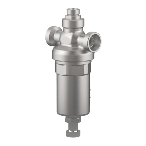
Operating and Installation Instructions Schematic Illustration of Combi-Regulator 1.1. Illustration 4186-1 Ø Locknut SW 30 Kontermutter SW 30 Set point screw SW 27 Einstellschraube SW 27 herose.com Page 4... -
Page 6: Illustration 4186-3
Operating and Installation Instructions 1.2. Illustration 4186-3 Locknut SW 19 Set point screw SW 14 herose.com Page 5... -
Page 7: General Information About These Operating Instructions
These Operating Instructions contain the instructions for the safe installation and operation of the valve in the proper manner. If difficulties occur, which cannot be resolved with the aid of these Operating Instructions, please contact HEROSE GMBH ARMATUREN UND METALLE for further information. -
Page 8: Safety Related Definitions
Remove residual medium. Leaking Regulator Hazard due to media escaping because of damaged seals or sealing surfaces. Protect the regulator from shocks and impacts, especially during transport and installation. Regularly check the regulator for leaks. herose.com Page 7... -
Page 9: Qualified Personnel
Technical Data 5.1. Purpose and Field of Use The HEROSE Combi-Regulator is used for automatic pressure regulation in fixed tanks for liquid and cryogenic technical gases. Without auxiliary energy, the Combi-Regulator ensures that in spite of temperature fluctuations, a constant, pre- defined specified pressure is maintained in the tank during the entire period of operation. -
Page 10: Function
Valves for use with oxygen are permanently marked with “O ”. Observe the max. P/T 30bar/60°C It is essential to consult HEROSE in case of use with media which require or exclude particular materials. Compatibility between the medium and the housing or sealing material is the responsibility of the operator. -
Page 11: Operating Data 4186-1
6.2. Information of Hazards During Installation, Operation and Maintenance Safe operation of the valve is only ensured if it is installed, commissioned and maintained by qualified personnel (see Section 3.4 "Qualified personnel") in accordance with the warning information in these Operating Instructions. herose.com Page 10... -
Page 12: Basic Installation Notes
The space inside the valve and the pressure vessel must be free of foreign bodies. Locknut At low or high surface temperatures, Set point screw appropriate protection must provided or the operating personnel must be informed. Figure 1: Installation position herose.com Page 11... -
Page 13: Product-Specific Installation Position And Installation Notes
Operating and Installation Instructions 6.5. Product-specific Installation Position and Installation Notes The HEROSE Combi-Regulator must be installed in the system according to the flow direction (AB) with the major axis – in which the two connections A and B are located – in a horizontal installation position without tension. During and after installation, connection C must point vertically upward. - Page 14 To adjust the nominal working pressure, loosen the lock nut and adjust the set point screw accordingly. Once the required nominal working pressure has been set, the set point screw must be secured again with the lock nut. herose.com Page 13...
-
Page 15: Maintenance And Repair Of The Valve
Repairs may only be performed by HEROSE or by specialist workshops authorised by HEROSE, with the exclusive use of original spare parts. The contact details for workshops authorised by HEROSE can be found on the HEROSE homepage (http://www.herose.com). -
Page 16: Other Applicable Documents
The scope and period of warranty is stated in the current version of the "General Terms and Conditions of Business of HEROSE GMBH" which is valid at the time of delivery, or in deviation from these, in the purchase contract. No warranty can... - Page 17 Operating and Installation Instructions herose.com Page 16...
-
Page 18: Notes
Operating and Installation Instructions 10. Notes herose.com Page 17...
Need help?
Do you have a question about the 4186 Series and is the answer not in the manual?
Questions and answers