
Related Manuals for Observator OMC-140

Summary of Contents for Observator OMC-140
- Page 1 OMC-140 Multifunctional NMEA display Operators’ Manual Version 1.08 - 2019 Author: Observator Instruments...
- Page 2 Correction DDC message, extra functionality v2.4 and up 1.08 Jan 2019 Update functionality V2.6 and up, some setting info moved to the Installation manual. Disclaimer: Observator Instruments reserves the right to improve their products and therefore specifications might change without prior notice. OMC-140 Operators’ Manual Page...
-
Page 3: Table Of Contents
Dimming possibilities ........................ 32 12.6 Dimensions (see drawings on following page) ................. 32 12.7 Alarms ............................33 12.8 In accordance with ........................33 Dimensional drawings ........................34 Menu structure Touch screen ......................35 Appendix: Declaration of Conformity ....................38 OMC-140 Operators’ Manual Page... - Page 4 Page intentionally left blank OMC-140 Operators’ Manual Page...
-
Page 5: Introduction
This manual is intended for the Operator of the display. An Operators Guide with the basic essential information is also available. For installation instructions we kindly refer to the Installation manual. The Installation manual also contains information for the system administrator. OMC-140 Operators’ Manual Page... -
Page 6: Safety
For outdoor use an IP66 or better housing is required. For correct functioning of this display the display and connected sensors must be installed according installation instructions as described in the OMC-140 Installation manual. Remember: instruments are tools. They do NOT replace your own observations! After end of life dispose this product according local regulations or return to manufacturer. -
Page 7: Display Functions
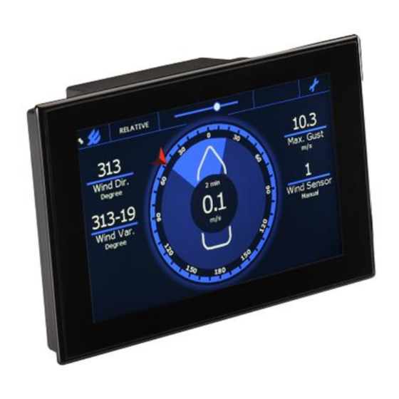
3 Display functions The examples used in this chapter display the default layout. It is possible to customize the layout by adding, removing parameters or change their position. 3.1 Home screen Wind Marine Display: Land Display: OMC-140 Operators’ Manual Page... -
Page 8: Home Screen 'Buttons
Wind direction variation over the selected average interval time. Also in the wind circle visualized in light blue: Shows max Gust over the selected interval time. If ‘Instant’ is selected it shows the Max Gust since last reset. Touch to reset OMC-140 Operators’ Manual Page... - Page 9 Heart beat. The dot should be running from left to right to indicate the display is working and not frozen. Wind direction variation over the selected average interval time. Average wind direction over the selected average interval. OMC-140 Operators’ Manual Page...
-
Page 10: Home Screen Gps Repeater
3.2 Home screen GPS repeater 3.2.1 Default Home screen functions: OMC-140 Operators’ Manual Page... -
Page 11: Touch Buttons
**Requires UTM data input (GMP)*. Speed and Course over ground (VTG)* Touching will switch to Arrow Speed display (Velocity & Drift) if available***. ***Requires Heading data input (HDT or THS)*. * Reference to the required NMEA input message OMC-140 Operators’ Manual Page... -
Page 12: Default Indicators
Heart beat. The dot should be running from left to right to indicate the display is working and not frozen. UTC time (GGA)* Number of Satellites (GGA)* Accuracy HDOP (GGA)* Differential Signal received YES / NO (GGA)* * Reference to the required NMEA input message OMC-140 Operators’ Manual Page... -
Page 13: Home Screen Heading
3.3 Home Screen Heading 3.3.1 Default Home screen functions: OMC-140 Operators’ Manual Page... -
Page 14: Touch Buttons
Only visible when an alarm is active. Touch this button to acknowledge the alarm. Heading from Gyro (THS or HDT)* Touch will toggle between Heading and Course Course Over Ground (VTG)* * Reference to the required NMEA input message OMC-140 Operators’ Manual Page... -
Page 15: Default Indicators
Heart beat. The dot should be running from left to right to indicate the display is working and not frozen. Speed Over Ground (VTG)* Course Over Ground (VTG)* * Reference to the required NMEA input message OMC-140 Operators’ Manual Page... -
Page 16: Home Screen Wind Airport
3.4 Home screen Wind Airport 3.5 Home screen Graph OMC-140 Operators’ Manual Page... -
Page 17: Home Screen Lightning
3.6 Home screen Lightning This is a dedicated screen for the BTD300 and BTD350 Thunderstorm detectors. Directional: Non-Directional: OMC-140 Operators’ Manual Page... - Page 18 On the General settings the Time Period and Units (Kilometers or Nautical Miles) can be set. The Indicator type can be set to No Direction in case your BTD Thunderstorm sensor doesn’t have a direction detector. OMC-140 Operators’ Manual Page...
-
Page 19: Home Screen Heading 2
This screen type is a Gyro repeater. The Gyro data is presented as dial gauge and numeric in the center. The 6 (or 4 in Portrait mode) other parameters are free to configure (See installation manual). OMC-140 Operators’ Manual Page... -
Page 20: Home Screen Speed Log
The water speed is displayed as dial gauge displayed numeric in the middle. The scale can de set to -5 .. 25 or -5 to 55 Knots. The 6 (or 4 in Portrait mode) other parameters are free to configure (See installation manual). OMC-140 Operators’ Manual Page... -
Page 21: Home Screen Rate Of Turn
3.9 Home screen Rate of Turn This screen displays the Rate Of Turn (derived from the gyro) as a dial gauge and numeric in the middle. OMC-140 Operators’ Manual Page... -
Page 22: General Settings Screen
Use ‘Save & Exit’ to store your changes and return to the Main screen. Otherwise use ‘Cancel’ to discard all changes and return to the Main screen. Display will also return to normal operation if no touch is detected for 1 minute. OMC-140 Operators’ Manual Page... -
Page 23: Average (Wind Only)
Normally wind information is reported in 10 minute average data. During specific changing conditions you will need to change to 2 minutes average. The OMC-140 can detect those conditions and change automatic between 10 & 2 minute average if ‘Marked Discontinuity’ is set in ‘Advanced Settings (default is off). - Page 24 Set the values for the ‘User’ settings at ‘Average’. For Wind Speed, Direction & Variation this is the Average interval in seconds. For Gust this is the reset time (Gust is always a 3s average). Valid values are 0 – 600 (seconds). OMC-140 Operators’ Manual Page...
-
Page 25: Advanced Functions
5.1 Wind display orientation Depending on available data the OMC-140 display is able to display the wind data up to 3 orientations in the marine mode. This mode is fixed during installation, in land mode only the True to North mode is available: a wind rose is displayed and the area between the logo and dim control bar will be empty. -
Page 26: Wind Orientation Reference Requirements
7 Data logging The OMC-140 Multifunctional NMEA display has a data logging function if enabled by the administrator. If this function is enabled Meteo data can be stored on a MicroSD card at a regular interval. -
Page 27: Terms, Abbreviations & Symbols List
Wind direction & speed as if the vessel would have no speed; True wind speed & direction related to the bow of the vessel. Wind Variation The variation in wind direction over the selected Average interval. OMC-140 Operators’ Manual Page... -
Page 28: Symbols
8.2 Symbols Select between Day or Night mode. In Night mode a darker color palette reduces the emitted light intensity. Brightness slider bar. In Automatic or NMEA control mode use this to set an offset. Settings menu OMC-140 Operators’ Manual Page... -
Page 29: Connections
NMEA output NMEA output Shield connection Micro USB connection for advanced programming and firmware updates. Display Bus Interconnection bus between displays Function Power input 1 Data input 1 Power input 2 Data input 2 Data output OMC-140 Operators’ Manual Page... -
Page 30: Dc Power Module Connections
10.3 Remote keypad and relay module Remote Keypad 1.. 5 not specified. Relay outputs Relay 1 NO contact Relay 1 Common Relay 1 NC contact Relay 2 NO contact Relay 2 Common Relay 2 NC contact OMC-140 Operators’ Manual Page... -
Page 31: Options
Default the remote is in Brightness control mode. If no button press has been detected for 10 seconds it will return to this mode. Toggles function in field left of the brightness slide bar. Example: Wind display: Relative, Theoretical & True OMC-140 Operators’ Manual Page... -
Page 32: Specifications
Central by means of NMEA DDC input 12.6 Dimensions (see drawings on following page) Packing 30 x 30 x 40 cm Weight 1.2 kgs (excl packing) Weight 3 kgs (incl packing & mounting materials) OMC-140 Operators’ Manual Page... -
Page 33: Alarms
12.7 Alarms Build-in alarms on parameters and system functioning Outputs, potential free relay outputs through optional OMC-140-2 module 12.8 In accordance with DNVGL-CG-0339 EMC Directive 2014/30/EU LV Directive 2014/35/EU RoHS Directive 2011/65/EU EMC: ESD IEC 61000-4-2; Radiated Immunity IEC 61000-4-3; Conducted Immunity IEC 61000- 4-6;... -
Page 34: Dimensional Drawings
13 Dimensional drawings OMC-140 Operators’ Manual Page... -
Page 35: Menu Structure Touch Screen
(Wind only) 10 minute 2 minute Instant User (settings from User Average Interval) Wind Speed (Wind only) km/h Wind Reference (Wind only) Relative Theoretical True User Average Interval (Wind only) Wind Speed Wind Direction Gust Wind Variation OMC-140 Operators’ Manual Page... - Page 36 Dimming Control (un)lock Sensor Selection (un)lock Wind Reference (un)lock (Wind only) System Name (GPS only) Edit GPS names (GPS only) Options Displays installed option boards Info Displays System & Product info. Front (only visible in Advanced Menu) OMC-140 Operators’ Manual Page...
- Page 37 Edit data fields in Front screen Sensors (only visible in Advanced Menu) NMEA VER Message Table OMC-140 Operators’ Manual Page...
-
Page 38: Appendix: Declaration Of Conformity
15 Appendix: Declaration of Conformity OMC-140 Operators’ Manual Page...
Need help?
Do you have a question about the OMC-140 and is the answer not in the manual?
Questions and answers