Advertisement
Quick Links
This product is suitable for installation in zones:
&
2
Outside Zone
All installations must comply with guidelines which are based on a zonal
concept. The diagram above illustrates this concept and must be followed
to ensure the safe installation of electrical appliances in the bathroom.
These regulations apply to domestic installations only. Installations must be
made in accordance with the current IEE wiring regulations and relevant
building regulations. HiB recommends that all electrical bathroom
products should only be fitted by a suitably qualified, Part P registered
electrician.
Installation
Before installation, ensure the domestic electrical mains supply to
which the cabinet is to be connected is turned off. Before drilling,
ensure that there are no hidden cables or pipes in the wall.
recommended that the fitting of this product is conducted by two people.
1. Before commencing installation, remove the door(s) from the carcass. This
is done by gently pulling at the tab at the back of each hinge, as
A. Carefully move the door away from the cabinet while gently extracting
the wire. Disconnect the cable connector and place the cabinet door(s)
carefully onto a soft surface where they will not get damaged during
installation.
2. Position the cabinet in a suitable location (according to the zonal diagram
(Fig. 1) above) ensuring that the mains supply cable is within reach of the
cable connection point of the cabinet. Carefully mark the desired position
of the cabinet using a soft pencil, ensuring it is level.
3. Remove the cabinet from the wall and using a spirit level, mark a horizontal
line below the pencil mark, taking into account the location of the
mounting points (Fig. B). Place brackets on the line paying attention to the
distance between the hangers on the cabinet. Carefully mark the position
Door Removal (Fig. A)
T:
+44 (0)20 8441 0352
F:
+44 (0)20 8441 0219
Building 3, North London Business Park, Oakleigh Road South, New Southgate, London. N11 1GN
©HiB Copyright: No part of this document may be reprinted or duplicated without HiB consent. All sizes and measurements are approximate, but we do try and make sure they are as accurate as possible. In the
interest of continuous product development, HiB reserves the right to alter specifications as necessary. E & OE.
(Fig. 1)
It is strongly
per Fig.
REAR VIEW
Mounting Points
Location of internal
xing hole (SINGLE DOOR)
Location of internal
xing hole (DOUBLE DOOR)
Fixing Brackets (Fig. B)
E:
sales@hib.co.uk
Thank you for purchasing this HiB product.
Please read through these instructions carefully and refer back to them
during installation to ensure that your product is fitted safely and that it
retains its high quality finish.
Please retain this leaflet for future reference.
of the holes using a soft pencil. (Fig. C).
4. Before drilling, ensure there are no hidden cables or pipes behind the
mounting point. Using a suitable drill bit, drill holes in the marked positions
to a suitable depth.
5. Insert wall plugs level with the surface of the wall. If fitting to a tiled surface,
wall plugs should be inserted below the tile surface to avoid cracking. NB.
For plasterboard walls, specialist fixings should be purchased from any DIY
or hardware store.
6. Fix the brackets to the wall using the screws provided.
7. Carefully remove the small screws along the top front edge of the cabinet
to gain access to the internal panel(s) (Fig. D) Keep screws in a safe place.
8. Temporarily hang the cabinet ensuring the claws on the hangers are
securely located on the wall brackets. Using a spirit level adjust the cabinet
via the screws on the hangers (Fig. D).
9. Mark the position of the internal fixing hole and remove the cabinet. Using
a suitable drill bit, drill a hole and insert a wall plug as per stage 4.
10. Connect the cable at the rear of the cabinet to the mains supply cable using
a suitable terminal block (not supplied) according to the wiring diagram
(Fig. 2) on the back page.
11. Rehang the cabinet in position, tighten the screws on the hangers (Fig. D)
and secure the base of the cabinet with the supplied screw(s) and screw
cap(s).
12. Insert the supplied shelf brackets into the appropriate holes on the inside
of the cabinet, depending on what height each shelf is required. Slide each
shelf into position and secure in place by tightening the small plastic grub
screw on the underside of each shelf bracket.
13. With help from a second person,
carefully connect the cable connector - take care to connect the wires in
the correct orientation. Once connected, carefully slide any excess wiring
and the connectors inside the carcass and reconnect the hinges. Hinges
are reconnected by clipping the front of the hinge in and then applying
pressure on the back of the hinge until an audible 'click' is heard.
14. Switch the mains supply back on.
Hanging Brackets (Fig. C)
hib.co.uk
FI#02 014 R170405
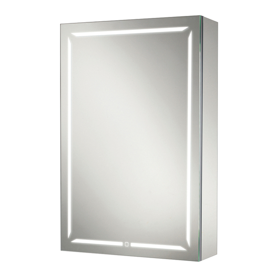
Groove Cabinets
Groove 50
Art No. 48400
Groove 60
Art No. 48500
Groove 80
Art No. 48600
offer the door up to the cabinet and
Angle Adjustment
Claw In/Out
Claw In/Out
Adjustment
Adjustment
Hanger Adjustment (Fig. D)
Ver No.
1.0 Jan 2017
Advertisement

Related Manuals for HiB Groove 50


Summary of Contents for HiB Groove 50
- Page 1 Building 3, North London Business Park, Oakleigh Road South, New Southgate, London. N11 1GN ©HiB Copyright: No part of this document may be reprinted or duplicated without HiB consent. All sizes and measurements are approximate, but we do try and make sure they are as accurate as possible. In the...
- Page 2 Building 3, North London Business Park, Oakleigh Road South, New Southgate, London. N11 1GN ©HiB Copyright: No part of this document may be reprinted or duplicated without HiB consent. All sizes and measurements are approximate, but we do try and make sure they are as accurate as possible. In the...