Table of Contents
Advertisement
Available languages
Available languages
Quick Links
Advertisement
Chapters
Table of Contents

Related Manuals for Comunello Automation BORDER 400

Summary of Contents for Comunello Automation BORDER 400
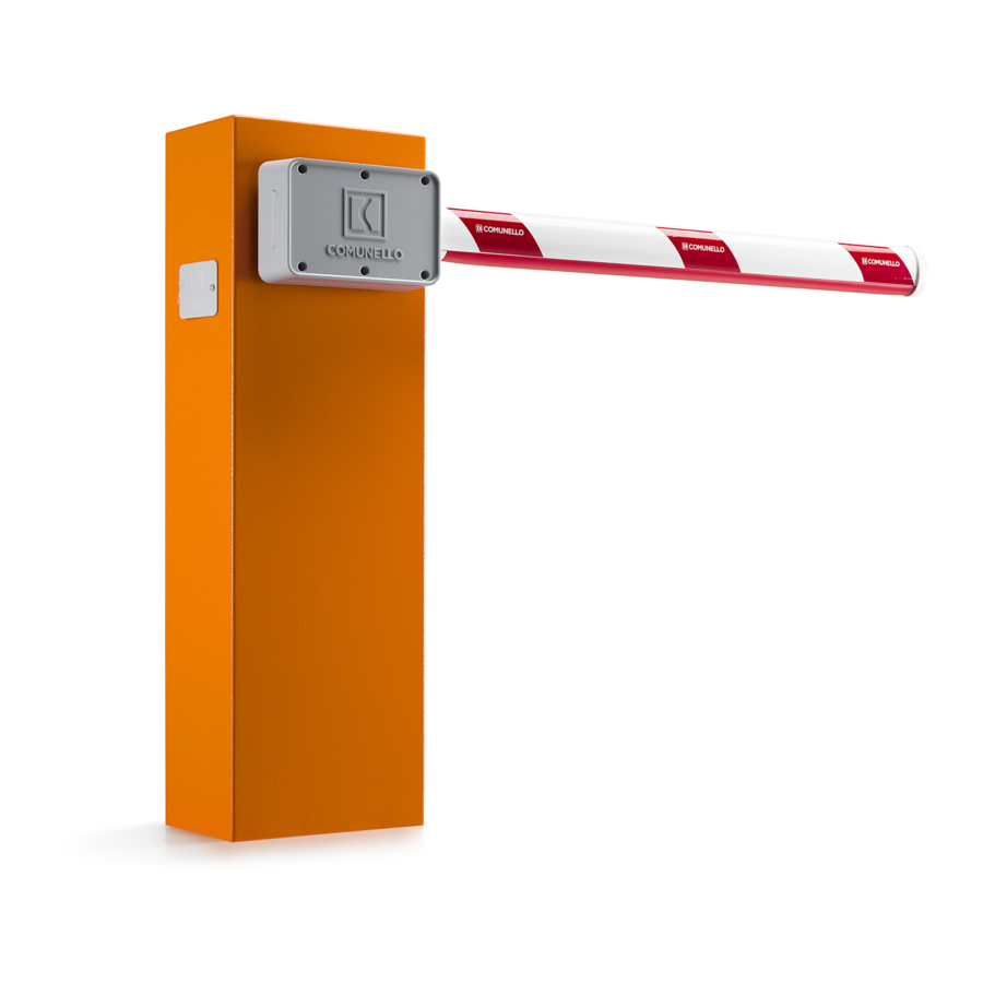
- Page 1 INSTALLATION AND USER’S MANUAL BORDER 400 Electromechanical road barrier system comunello.com ISTRUZIONI D’USO E DI INSTALLAZIONE INSTALLATIONS-UND GEBRAUCHSANLEITUNG INSTRUCIONS D’UTILISATION ET D’INSTALLATION INSTRUCCIONES DE USO Y DE INSTALACION 91300187 Rev. 05 - 11.06.18...
- Page 2 FIG. 1 BORDER 400 FIG. 2 FIG. 3A BORDER 400 FIG. 3B COMUNELLO ®Copyright 2017 - All rights reserved...
- Page 3 FIG. 4 FIG. 5 FIG. 6 FIG. 7 BORDER 400 BORDER 400 COMUNELLO ®Copyright 2017 - All rights reserved...
- Page 4 FIG. 8A FIG. 8B FIG. 8D FIG. 8C COMUNELLO ®Copyright 2017 - All rights reserved...
- Page 5 FIG. 9A FIG. 9B FIG. 10A FIG. 10B COMUNELLO ®Copyright 2017 - All rights reserved...
- Page 6 FIG. 11A FIG. 11C FIG. 11B FIG. 12A FIG. 12B FIG. 12C...
- Page 7 FIG. 13A FIG. 14 FIG. 13B COMUNELLO ®Copyright 2017 - All rights reserved...
- Page 8 FIG. 15 FIG. 16 A FIG. 16 B...
- Page 9 FIG. 17A FIG. 17B FIG. 17C FIG. 17D COMUNELLO ®Copyright 2017 - All rights reserved...
- Page 10 24 V BATTERIA TAMPONE 24 V BATTERY TRASFORMATORE TRANSFORMER LAMPEGGIANTE 230 / 21,7V - 7,5A FLASHING LIGHT MOTORE 1 MOTOR 1 INGRESSO BLOCCO (N.C.) INPUT BLOCK (N.C.) ALIMENTAZIONE FOTOCELLULE PHOTOCELL POWER FINECORSA CHIUSURA (N.C.) END CLOSE (N.C.) FINECORSA APERTURA (N.C.) END OPEN (N.C.) PULSANTE APRI-CHIUDI (N.O.)
- Page 11 ISTRUZIONI D’USO E DI INSTALLAZIONE BORDER 400 / 600 DICHIARAZIONE DI CONFORMITÁ CE Il sottoscritto, sig. COMUNELLO LUCA rappresentante il seguente costruttore F.lli COMUNELLO spa Via Cassola 64, 36027 Rosà (VI) Italy DICHIARA che l’apparecchiatura descritta in appresso: Descrizione Automazione elettromeccanica per barriera...
- Page 12 INDICE AVVERTENZE PER L’USO • Non eseguire modifiche su nessuna parte se non AVVERTENZE GENERALI previste nel presente manuale. Operazioni di questo Avvertenze per la sicurezza tipo possono solo causare malfunzionamento. Il Avvertenze per l’installazione Avvertenze per l’uso costruttore declina ogni responsabilità per danni MODELLI E DESCRIZIONE PRODOTTO derivati da prodotti modificati.
- Page 13 • Inserire completamente la guaina paracolpi e il tappo senza avvitarlo. orizzontale" (FIG. 8A) e che il meccanismo interno sia nella posizione • Per l’asta BORDER 400, posare l’appoggio mobile per poter facilmente illustrata in FIG. 8B. Utilizzare il frenafiletti nelle 4 viti centrali.
- Page 14 componenti elettrici esterni alla centralina deve Con le apposite viti fissare l’appoggio mobile alla piastra forata, dopo averla inserita sopra la parte inferiore dell’asta (FIG. 16B). essere effettuato secondo quanto prescritto • Rimontare il tappo all'estremità dell'asta. dalla normativa EN 60204-1 e dalle modifiche 5 RIMOZIONE DEL TABLET a questa apportata dal punto 5.2.7 della EN 12453.
- Page 15 per il comando manuale deve essere fatto delle prescrizioni potrebbe provocare danni e posizionando la pulsantiera in modo che l’utente gravi incidenti. non venga a trovarsi in posizione pericolosa. Esaminare frequentemente l’impianto per rilevare • Il motoriduttore usato per muovere la barriera eventuali segni di danneggiamento.
- Page 16 2 di EN 13849-1 viene eseguito prima di ogni manovra un test delle 1. CODE (Codice del radiocomando): fotocellule. Per poter eseguire questo test è indispensabile alimentare La centrale permette di memorizzare fino a 120 radiocomandi aventi codice la trasmittente di ogni coppia di fotocellule mediante l’apposita uscita di diverso fra loro di tipo fisso o rolling code.
- Page 17 “MAX” (ovvero uguale alla regolazione impostata tramite il trimmer SPEED, La centrale nella configurazione di default presenta la logica di “ASTA A LED L5 spento), se si desidera modificare il profilo ad un valore Medio SINISTRA”(Fig.10B); se occorre abilitare la logica di “ASTA A DESTRA” “MED”...
- Page 18 La centrale permette di impostare il funzionamento “Chiudi Sempre”: tale Nella configurazione di fabbrica è selezionato il livello 3. funzione, programmabile solo se è già stato programmato un Tempo di Pausa, interviene dopo una mancanza di alimentazione; se viene 12 RESET rilevato che la barriera è...
- Page 19 (fattura fiscale) a COMUNELLO. Il Cliente deve denunciare il difetto a COMUNELLO entro il termine di decadenza di 30 (trenta) giorni dalla scoperta. L’azione deve essere esercitata entro il termine di prescrizione di 6 (sei) mesi dalla scoperta. I pezzi dei Prodotti per i quali viene richiesta l’attivazione della Garanzia Convenzionale devono essere spediti dal Cliente presso FRATELLI COMUNELLO SPA, Via Cassola 64, 36027 Rosà...
- Page 20 INSTALLATION AND USER’S MANUAL BORDER 400 / 600 EC DECLARATION OF COMFORMITY: The undersigned Mr. Luca Comunello, representing the following manufacturer, Fratelli COMUNELLO Spa Via Cassola 64, 36027 Rosà (VI) – Italy DECLARES that the equipment described below: Description: Electromechanical automation for barrier system...
-
Page 21: Table Of Contents
CONTENTS BORDER barrier system in consideration of the GENERAL PRESCRIPTIONS specific application. Safety prescriptions • The automation system must not be used until Installation prescriptions Operating prescriptions the transit area has been made safe. MODELS AND PRODUCT DESCRIPTION • Dispose of packaging materials in compliance Description Typical installation with local regulations. -
Page 22: Typical Installation
(FIG. 8D). B PHOTOCELLS Fitting the springs: C FLASHING LIGHT The BORDER 400 barrier system is equipped with single spring mechanism, D KEY SELECTOR SWITCH Depending on the accessories and on the lenght of the arm, the spring E END REST can be installed in the first or in the second hole of the spring stretcher tool. -
Page 23: Manual Release
11.1 PRESCRIPTIONS • If in the opening position the arm doesn't look vertical to the ground, adjust the bolt, marked in FIG. 13B. • Once the arm is adjust, fasten back the bolts. • The control unit is not equipped with a device for 4.4.3 MANUAL RELEASE disconnection of the 230 Vac power supply line. -
Page 24: Technical Characteristics
and secure manner. least in case they are supervised or educated on • The rear of the box is equipped with knockouts the operation and its use. for wall fixing (knockouts for fixing holes using • Do not allow the children to play with the device anchor bolts or holes for fixing with screws). -
Page 25: Programming
EMERGENCY STOP INPUT: SET key: programs the information in accordance with the function type The control unit allows the connection of an emergency stop pushbutton preselected with the SEL key. (NC). Pressing this pushbutton irrespective of the current operating mode IMPORTANT: The SET key function can be replaced by the remote if of the control unit will cause barrier movements to stop immediately. - Page 26 proceed as follows: use the SEL key to select blinking LED L4 and press the as described above for LED L1 in the main menu. If you wish to enable SET key; at the same time LED L4 becomes steady on and programming the remote programming function, proceed as follows: ensure you have will be completed.
-
Page 27: Reset
select blinking LED L2 and press the SET key; LED L2 becomes steady on If you need to reset the control unit to restore the factory settings, press the and programming will be completed. Repeat the procedure if you wish to SEL and SET keys together;... - Page 28 f) The Customer cannot claim compensation for indirect damage, loss of profits, loss of production and in any case it cannot claim compensation for an amount that exceeds the value of the supplied components or products. All transport costs for Products that have been repaired or to be repaired, although covered by the Conventional Warranty, shall be charged to the Customer.
- Page 29 INSTALLATIONS-UND GEBRAUCHSANLEITUNG BORDER 400 / 600 CE-KONFORMITÄTSERKLÄRUNG Der Unterzeichner, Herr COMUNELLO LUCA, der den folgenden Hersteller vertritt: F.lli COMUNELLO spa Via Cassola 64, 36027 Rosà (VI) Italy ERKLÄRT, dass die anbei beschriebene Ausrüstung: Beschreibung Elektromechanische Automatisierung für Schrankenanlagen Modell BORDER 400 / 600 den Gesetzesbestimmungen entspricht, die folgende Richtlinien umsetzen: •...
- Page 30 INHALTSVERZEICHNIS GEBRAUCHSHINWEISE ALLGEMEINE HINWEISE Sicherheitshinweise • Es dürfen nirgendwo Änderungen durchgeführt Installationshinweise werden, sofern nicht in diesem Handbuch Gebrauchshinweise vorgesehen. Arbeiten dieser Art können lediglich MODELLE UND PRODUKTBESCHREIBUNG Betriebsstörungen verursachen. Hersteller Beschreibung Typische Installation übernimmt keine Verantwortung für Schäden, die von TECHNISCHE EIGENSCHAFTEN DES PRODUKTS veränderten Produkten herführen.
-
Page 31: Installation
• Die Feder (Einzel- oder Doppelfeder) oben und unten befestigen, gemäß PRODUKTS Abb. 12A und 12B. • Sicherstellen, dass nach erfolgter Installation der Baum von der Feder ausgeglichen wird, wie in den Abb. 14 dargestellt. BORDER 400 • Aus folgender Tabelle die geeignete Feder auswählen: Motorspeisung 24 V Maximale Leistungsaufnahme... -
Page 32: Prüfung
für die Anschlüsse mit Netzspannung (230V) als abnehmen (Abb. 4). • Die Stromleiter zur Elektronikkarte führen. auch für die in SELV-Schutzkleinspannung. Für die Verkabelungen in Niederspannung (230V) 7 PRÜFUNG und die der Schutzkleinspannung (SELV) sind Bei der Prüfung von BORDER sind die folgenden Arbeitsschritte erforderlich: ausschließlich getrennte Führungsschienen aus •... -
Page 33: Technische Eigenschaften
garantiert damit den Quetschschutzvorrichtungen 11.2 TECHNISCHE EIGENSCHAFTEN • Eingang Not-Akku: 24 V 7A/h min. der Kategorie 2 einen Schutz vor Defekten gemäß • Ausgang Blinkleuchte: 24 V 4 W max. Punkt 5.1.1.6. der Richtlinie EN 12453. Wenn die • Ausgänge Motoren: 1 x 50 W max. -
Page 34: Programmierung
EINSTELLUNG DER MOTORKRAFT BEIM „NORMALZYKLUS“: unterschiedlichen Codes (Festcode oder Rolling Code) gespeichert werden. Die elektronische Steuerung ist mit einem Trimmer „SPEED“ für die Programmierung. Einstellung der Motorkraft beim Normalzyklus ausgestattet. Zur Programmierung des Übertragungscodes: Mit der Taste SEL auf das Blinken Die Einstellung kann beim Normalzyklus in einem Bereich von 50% bis der LED L1 stellen, den gewählten Code innerhalb von 10 Sekunden mit der 100% der max. - Page 35 das Profil auf einen Mindestwert „MIN“ geändert werden soll, den oben vorherige Konfiguration den Vorgang wiederholen. beschriebenen Vorgang durch zweimaliges anstatt einmaliges Drücken der Taste SEL wiederholen (danach wird die LED L5 schnell blinken). Zur 3. AUTOMATISCHE PROGRAMMIERUNG: Rückstellung auf die ursprüngliche Konfiguration den Vorgang wiederholen. Die Steuerung ermöglicht die folgende Automatische Programmierung 6.
-
Page 36: Reset
freigegeben wurde (wird vom Blinken 1 1 0 1 1 0 der LED LEV angezeigt), aller zuvor gespeicherten Funksteuerungen und der Regel der ersten Funksteuerung. mit der Taste SEL auf das Blinken der LED L3 stellen und auf die Taste SET drücken: Die LED L3 schaltet permanent ein und der Vorgang wird beendet. - Page 37 INSTRUCIONS D’UTILISATION ET D’INSTALLATION BORDER 400 / 600 DÉCLARATION DE CONFORMITÉ CE Le soussigné, M. COMUNELLO LUCA, représentant le suivant constructeur F.lli COMUNELLO spa Via Cassola 64, 36027 Rosà (VI) Italie Déclare que l’appareil décrit ci-dessous: Description Automatisme électromécanique pour barrière Modèle...
- Page 38 SOMMAIRE normes locales. AVERTISSEMENTS GÉNÉRAUX Avertissements concernant la sécurité AVERTISSEMENTS CONCERNANT Avertissements concernant l’installation L’UTILISATION Avertissements concernant l’utilisation • N’effectuer aucune modification quelque MODÈLES ET DESCRIPTION PRODUIT composant que ce soit, sauf prévue dans ce manuel. Description Installation type Ce type d’intervention est uniquement susceptible CARACTÉRISTIQUES TECHNIQUES DU PRODUIT d’entraîner des dysfonctionnements.
-
Page 39: Caractéristiques Techniques Du Produit
• Placer la lisse en position verticale (FIG. 11). • Au-dessus et au-dessous, fixer le ressort (simple ou double) comme indiqué sur les FIG. 12A et 12B. BORDER 400 • Une fois l'installation effectuée, s'assurer que la lisse est contrebalancée Alimentation moteur 24 V par le ressort comme indiqué... -
Page 40: Entretien
SELV. Utiliser exclusivement des canalisations en Pour le contrôle technique de l'automatisme BORDER, procéder aux plastique, différentes pour les câblages à basse opérations suivantes : tension (230V) et pour les câblages à très basse • S’assurer que toutes les instructions figurant dans le présent manuel et en particulier dans le chapitre 1 «Recommandations générales»... -
Page 41: Caractéristiques Techniques
12453. Aussi, dans le cas où les dispositifs de • Émetteurs op.: 18 Bit ou Rolling Code • Codes TX max. en mémoire: 120 (CODE ou CODE PED) sécurité ne seraient pas branchés ou dans le cas • Dimensions carte: 100x105 mm. -
Page 42: Programmation
de la Force maximale pendant le cycle normal. l’opération de programmation, tous les LED de programmation se mettent à clignoter pour indiquer qu'aucune autre mémorisation n'est possible. RALENTISSEMENT: Effacement des radiocommandes. La fonction de ralentissement est utilisée pour éviter la butée à grande Pour effacer toutes les radiocommandes précédemment mémorisées dans vitesse au terme de la phase d'ouverture et fermeture. - Page 43 Répéter l’opération pour rétablir la configuration initiale. le clignotement 1 0 1 0 1 du led n°8); à l'aide de la touche SEL, faire clignoter le LED N°3; maintenir enfoncée la touche SET: l’unité électronique 6. SLOWING OPEN (Sélection du profil Force en cycle Ralenti d’ouverture): complète la phase d’auto-programmation en effectuant une ouverture et L’unité...
-
Page 44: Reset
L’unité électronique permet de sélectionner le fonctionnement «Follow me»: cette fonction, programmable uniquement si le temps de Pause a déjà été 13 DIAGNOSTIC programmé, prévoit la réduction du temps de Pause en le ramenant à 5 sec. une fois que la cellule photoélectrique DS1 est libérée; à savoir que la Test Cellule photoélectrique: lisse se referme 5 sec. - Page 45 INSTRUCCIONES DE USO Y DE INSTALACION BORDER 400 / 600 DECLARACIÓN DE CONFORMIDAD CE El abajo firmante, Señ. COMUNELLO LUCA, representante el siguiente fabbricante F.lli COMUNELLO spa Via Cassola 64, 36027 Rosà (VI) Italia Declara que el automatismo en lo sucesivo descrito: Automatismo electromecánico para barrera...
- Page 46 ÍNDICE ADVERTENCIAS DE USO ADVERTENCIAS GENERALES • No realice modificaciones en ninguna pieza si no Advertencias de seguridad estuviera previsto en este manual. Las operaciones de Advertencias de instalación este tipo pueden provocar fallos de funcionamiento. Advertencias de uso El fabricante declina toda responsabilidad por daños MODELOS Y DESCRIPCIÓN DE LOS PRODUCTOS causados por productos modificados.
- Page 47 • Asegúrese de que al concluir la instalación el mástil esté E APOYO PARA MÁSTIL contrabalanceado por el muelle, como se muestra en la FIG. 14 • Escoja el muelle adapto consultando la siguiente tabla 3 CARACTERÍSTICAS TÉCNICAS BORDER 400 BORDER 400 BAR ASSEMBLY LENGTH (meters) AND SPRING CHOICE 1,5 2,0 2,5 3,0 3,5 4,0 Alimentación motor...
- Page 48 de los conductores de la tensión de red, o deben • Compruebe uno por uno el funcionamiento correcto de todos los dispositivos de seguridad montados en el sistema (fotocélulas, bandas estar aislados adecuadamente con un aislamiento sensibles, dispositivos de parada de emergencia, etc.). adicional de al menos 1 mm de espesor.
- Page 49 experiencia o sin los conocimientos necesarios, FCC: Entrada Final de carrera Cierre Motor (NC). GND: Entrada GND común. siempre y cuando estén controladas o hayan FCA: Entrada Final de carrera Apertura Motor (NC). recibido las instrucciones necesarias para utilizar de DS1: Entrada Dispositivo de Seguridad (NC).
- Page 50 2. MOTOR TIME (Program. tiempo de funcionamiento de la barrera): FUNCIONAMIENTO CON TEMPORIZADOR: El cuadro de control incorpora de fábrica un perfil de trabajo estándar. El cuadro de control permite conectar un temporizador en lugar del Si tuviera que modificar el tiempo de trabajo del Motor y la duración de pulsador de mando abrir –...
- Page 51 es igual a la regulación configurada mediante el menú SLOWING, LED 5. DS1 DURANTE APERTURA: L7 apagado), si se quiere modificar el perfil con un valor Medio “MED” El cuadro de control permite modificar el funcionamiento de la entrada proceda de la siguiente manera: colóquese con el pulsador SEL en el LED DS1.
- Page 52 a) Esta garantía, en lo que se refiere a las relaciones salida de la luz intermitente se activará siempre 3 segundos antes de que el automatismo comience cualquier movimiento. Repita la operación si desea comerciales o en caso de venta de bienes para uso restablecer la configuración original.
- Page 53 NOTES COMUNELLO ®Copyright 2017 - All rights reserved...
- Page 54 FRATELLI COMUNELLO S.P.A. AUTOMATION GATE DIVISION Via Cassola, 64 - C.P. 79 36027 Rosà, Vicenza, Italy Tel. +39 0424 585111 Fax +39 0424 533417 info@comunello.it www.comunello.com...
Need help?
Do you have a question about the BORDER 400 and is the answer not in the manual?
Questions and answers