Table of Contents
Advertisement
Quick Links
Advertisement
Table of Contents

Summary of Contents for Analogic DBS9900
- Page 1 (217) 352-9330 | Click HERE Find the Analogic DBS9900 at our website:...
- Page 2 High-Performance VXI Carrier User’s Manual Revision 01 Artisan Technology Group - Quality Instrumentation ... Guaranteed | (888) 88-SOURCE | www.artisantg.com...
- Page 3 DBS9900 User’s Manual Proprietary Statement The information contained in this publication is derived in part from proprietary and patent data of the Analogic Corporation. This information has been prepared for the express purpose of assisting operating and maintenance personnel in the efficient use of the instrument described herein. Publication of this information does not convey any rights to reproduce it or to use it for any purpose other than in connection with the installation, operation, and maintenance of the equipment described herein.
- Page 4 Repairs to the product and/or its components have not been made by anyone other than Analogic or one of its authorized repair agents. g) The product has not been modified, altered, or changed in any manner by anyone other than Analogic or one of its authorized repair agents.
- Page 5 Definition I/0 1, I/0 2 Also called daughterboards, and/or modules. There can be one or two modules installed in the DBS9900. I/O 1 refers to the first installed module and I/O 2 refers to the second. DBS901 Arbitrary Waveform Generator daughterboard (purchased separately).
- Page 6 DBS9900 User’s Manual Safety Precautions Warnings and Cautions The terms WARNING and CAUTION have specific meanings in this manual: WARNING A WARNING advises against certain actions or situations that could result in personal injury or death. CAUTION A CAUTION advises against actions that could damage equipment, produce inaccurate data or invalidate a procedure.
- Page 7 WARNING Do not install substitute parts or perform any unauthorized modifications to this unit. Return the unit to Analogic for service and repair to ensure that the safety features are maintained. AVERTISSEMENT - NE PAS SUBSTITUER LES PIÈCES OU MODIFIER L’UNITÉ...
-
Page 8: Table Of Contents
Software Installation ............................2-6 2.6.1 Installation Steps Start-Up and Verification ............................. 2-6 2.7.1 Self-Test DBS9900/Module Pin Connections ........................2-7 DBS9900 26 Pin Control Connector ........................2-8 Operation......................... 3-1 Sample Clock and Timebase ..........................3-2 3.1.1 Possible Clock Configurations 3.1.2 Internal Sample Clock Parameters 3.1.3... - Page 9 DBS9900 Sample Clock Panel..........................4-3 4.2.1 Sample Clock Field Descriptions DBS9900 Trigger Panel ............................4-6 4.3.1 Trigger Panel Field Descriptions DBS9900 Driver Software – Description of Functions ..........5-1 Initialize, Module and Close Functions........................ 5-1 5.1.1 Initialize an9900_init 5.1.2 VIT Initialize an9900_VITinit 5.1.3...
- Page 10 5-62 5.7.6 Error Message an9900_errorMessage 5-63 DBS9900 VME / VXI Bus Interface - Registers ..............6-1 ID REGISTER 0x00 Read Only Logical Address Register ................. 6-3 DEVICE TYPE REGISTER ..........................6-3 Control Register ..............................6-5 Status Register..............................6-5 Memory Offset Register............................6-6 Memory Attribute Register ..........................
- Page 11 DBS9900 User’s Manual 6.12 JTAG Programming Register..........................6-11 Clock..........................7-1 Channel A/B Clock Selection: ..........................7-1 Frequency Synthesizer: ............................7-1 Time Base Divider: .............................. 7-1 Program Sequence:............................... 7-1 7.4.1 Sample Rate Calculation: Phase Lock Loop..............................7-3 LMX2306 Communications port ......................... 7-3 7.6.1...
-
Page 12: Overview
1 Overview 1.1 Introduction The Analogic DBS9900 is a high-speed, VXI ‘C’ size module. The DBS9900 accepts one or two daughterboards (called modules) from the DBS 9xx family of high-speed, high precision waveform generators and digitizers. Each module contains the circuitry necessary to operate independently for a complete channel of analog input or output. -
Page 13: Technical Support
Our Customer Service Coordinator will provide you a Customer Service Order number (CSO) that is an internal Analogic tracking number. The Service Coordinator will also inform you of the Warranty or Non-Warranty status of the units being returned, and the repair charge, if any. - Page 14 DBS9900 User’s Manual Your cooperation in contacting Analogic, Customer Service, and including the CSO Number with your return, as requested above, will allow us to properly track your returned goods and expedite repair and return. DBS9900 User’s Manual 82-28993 Revision 01...
- Page 15 DBS9900 User’s Manual DBS9900 User’s Manual 82-28993 Revision 01 Artisan Technology Group - Quality Instrumentation ... Guaranteed | (888) 88-SOURCE | www.artisantg.com...
-
Page 16: Preparation & Installation
Idle. 4 liters/minute Volts Amps Watts 0.00 0.00 0.01 0.04 0.70 -5.2 0.98 0.64 Supply Power Draw = 10.4 Watts DBS9900 Preparation & Installation 82-28993 Revision 01 Artisan Technology Group - Quality Instrumentation ... Guaranteed | (888) 88-SOURCE | www.artisantg.com... -
Page 17: Front Panel Connectors And Indicators
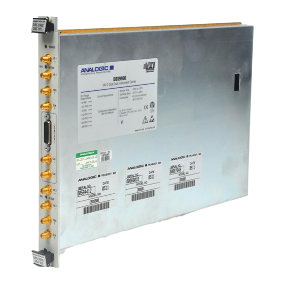
DBS9900 User’s Manual 2.4 Front Panel Connectors and Indicators The DBS9900 Front Panel is shown below. I/O 1, I/O 2, CAL, CLK and TRIG are SMA connectors. An additional 26 pin, 3-row D connector is provided for module specific I/O. There are three LED indicators on the front panel. They are POWER, CH 1 ACTIVE, and CH 2 ACTIVE. - Page 18 Note: All outputs are 50 ohm impedance. All inputs are high impedance. Reserved Reserved Figure 2-2 Front Panel 26 Pin Connector DBS9900 Preparation & Installation 82-28993 Revision 01 Artisan Technology Group - Quality Instrumentation ... Guaranteed | (888) 88-SOURCE | www.artisantg.com...
-
Page 19: Hardware Installation
When selecting the appropriate VXI chassis, ensure that it meets the cooling and power requirements specified below. This instrument can be installed in any VXI chassis slot except Slot One empty slot is required. The DBS9900 should be FIRMLY inserted into the slot to ensure proper operation. 2.5.2 The DBS9900 Logical Address Registers in VXIbus devices are located in the A16 address space (within 64 byte blocks). -
Page 20: A16, A24 And A32 Communications Mode
A24 mode. To operate in A16 mode, do not set any jumpers. In order to change this setting the DBS9900 boards must be removed from their case to access the jumpers. Proceed with caution. -
Page 21: Software Installation
DBS9900 User’s Manual 2.6 Software Installation The DBS9900 software is capable of interfacing with a host system via one of the following options: • Soft Front Panel • .DLL (for application programming) – Plug and Play driver functions • Direct manipulation of the hardware registers on the board (This is not recommended. -
Page 22: Dbs9900/Module Pin Connections
DBS9900 User’s Manual 2.8 DBS9900/Module Pin Connections NAME DESCRIPTION TYPE # PINS D[15:0] Bidirectional data bus A[22:0] Address bus in units of words Write Defines write cycle /strobe Enables data for read clocks write data /msel Identifies I/O cycle as memory... -
Page 23: Dbs9900 26 Pin Control Connector
DBS9900 User’s Manual 2.9 DBS9900 26 Pin Control Connector Description Description Description Mod. B - 1 Mod. B - 3 Mod. B - 6 Mod. B - 2 Mod. B - 4 Mod. B - 7 Mod. B SYNC Mod. B - 5 Mod. -
Page 24: Operation
DBS9900 User’s Manual 3 Operation The DBS9900 High-Performance VXI Carrier provides the structure, power, clock and trigger functionality for use with many different types of plug-in daughterboard modules. Features include: • A programmable threshold External Clock is supplied to each module through front panel connectors (labeled CLK1 and CLK2) to control the sample rate. -
Page 25: Sample Clock And Timebase
DBS9900 User’s Manual 3.1 Sample Clock and Timebase The DBS9900 provides the required timebase (Reference Clock) for both installed modules. The limits of the frequency range are 60Hz to 100MHz depending on the plug-in module. An Internal Sample Clock may be used for either one or both of the plugin modules. Additionally, independent External Sample Clocks can configured for each or both modules. -
Page 26: Internal Sample Clock Parameters
DBS9900 carrier. • The DBS9900 internal timebase is capable of a 60Hz to 100MHz range. The type(s) of plug- ins may restrict the use of this entire range. The DBS9900 will calculate an Actual Frequency to a maximum error of better than 0.5% from the Desired Frequency. -
Page 27: Performance Specification
DBS9900 User’s Manual 3.2 Performance Specification 3.2.1 ANALOG I/O Number of Channels: One single ended or differential I/O port for each plug-in module via front panel mounted SMA connectors. Signal Amplitude: See DBS 9XX plug-in module specifications. Impedance: (Dependent on modules installed). -
Page 28: Control Outputs
DBS9900 User’s Manual Waveform: 5 µs min. pulse width. May be dependent on module installed. Overvoltage Protection: ± 20V max. External Reference for PLL: Inputs: One front-panel-mounted SMA connector shared with channel B external clock input. Frequency Range: 10 MHz ± 1%. -
Page 29: Power
DBS9900 User’s Manual 3.2.5 POWER Total Power Dissapation: 20W max. + installed module power. DBS 9900 Power Consumption Profile: DBS 9900 Only Idle Volts Amps Watts 0.00 - 24 0.00 0.01 - 12 0.04 0.70 - 5.2 0.98 0.64 Total 10.4... -
Page 30: Emc & Safety Agency Compliance
DBS9900 User’s Manual ® VXI plug&play compliant for Windows 95 and NT. ® Written using LabWindows CVI Source code is included as well as .DLL files to allow porting to most popular programming environments. Source code is also provided with the fully functional soft front panels. - Page 31 DBS9900 User’s Manual DBS9900 Operation 82-28993 Revision 01 Artisan Technology Group - Quality Instrumentation ... Guaranteed | (888) 88-SOURCE | www.artisantg.com...
-
Page 32: Using The Dbs9900 Soft Front Panel
The DBS9900 Soft Front Panel can be used to control the instrument and perform basic operations. 4.1 DBS9900 Main Panel The DBS9900 Main Panel is the first screen to appear when the DBS9900 Soft Front Panel software is opened. From this panel, the following operations may be performed: •... -
Page 33: Main Panel Field Descriptions
“Available Instruments” display. If a DBS9900 was previously initiated, the initiate button brings up the message; “DBS9900 at LAxx already initiated”. An “OK” button in the message box allows the message to disappear. -
Page 34: Dbs9900 Sample Clock Panel
DBS9900 User’s Manual 4.2 DBS9900 Sample Clock Panel The DBS9900 Sample Clock Panel may be accessed from the Main Panel or via the Sample Clock button on any other panel. From this panel, the following operations may be performed: •... - Page 35 DBS9900 User’s Manual Figure 4-2 DBS9900 SFP Sample Clock Panel DBS9900 Soft Front Panel 82-28993 Revision 01 Artisan Technology Group - Quality Instrumentation ... Guaranteed | (888) 88-SOURCE | www.artisantg.com...
-
Page 36: Sample Clock Field Descriptions
Three position target switch that selects “Internal” or “External” clock input or “External Ref” for the PLL 10MHz reference signal. Note that the reference signal can be applied only to the “CLK 2” input on the DBS9900 front panel. Default is ‘Internal”. -
Page 37: Dbs9900 Trigger Panel
DBS9900 User’s Manual 4.3 DBS9900 Trigger Panel All of the following controls are duplicated in both the I/O-1 and I/O-2 boxes. Figure 4-3 DBS9900 SFP Trigger Panel DBS9900 Soft Front Panel 82-28993 Revision 01 Artisan Technology Group - Quality Instrumentation ... Guaranteed | (888) 88-SOURCE | www.artisantg.com... -
Page 38: Trigger Panel Field Descriptions
“The TTLTRG or ECLTRG line you selected is already in use. Please select another line or change the selection previously made.” DBS9900 Soft Front Panel 82-28993 Revision 01 Artisan Technology Group - Quality Instrumentation ... Guaranteed | (888) 88-SOURCE | www.artisantg.com... - Page 39 DBS9900 User’s Manual DBS9900 Soft Front Panel 82-28993 Revision 01 Artisan Technology Group - Quality Instrumentation ... Guaranteed | (888) 88-SOURCE | www.artisantg.com...
-
Page 40: Dbs9900 Driver Software - Description Of Functions
DBS9900 User’s Manual 5 DBS9900 Driver Software – Description of Functions WARNING The application software that uses this driver should not try to access 9900 registers directly. Using functions other than those provided by this driver to access 9900 registers may end in unexpected results. - Page 41 DBS9900 User’s Manual 5.1.2 VIT Initialize an9900_VITinit This function is used only for the Soft Front Panel and performs the following initialization actions: • Opens a session to the Default Resource Manager resource and a session to the specified device using the interface and address specified in the Resource_Name control.
- Page 42 DBS9900 User’s Manual VI_OFF (0) Don’t Reset VI_ON (1) Reset Device (Default Value) Notes: If you do not want the instrument reset. Set this control to Don’t Reset while initializing the instrument. instrumentHandle ViSession This control returns an Instrument Handle that is used in all...
- Page 43 Set Module an9900_setModule The DBS9900 can host two modules, any combination of DBS901s and DBS902s. Some DBS9900 functionality, such as clock generation is common to both modules, whereas other functionality such as clock and trigger source selection can be controlled on a per-module basis.
- Page 44 DBS9900 User’s Manual <RETURN> ViStatus “VI_SUCCESS” > 0 Warning: The function completed, but an exception condition occurred which may require attention. < 0 Error: The function did not complete successfully. 5.1.5 Identify Module an9900_identifyModule This function specifies whether a given module is a DBS901, a DBS902 or is not installed. By calling this function twice, once with each AN9900_MODULE value, a program can determine which plug-in daughterboards are installed.
- Page 45 DBS9900 User’s Manual 5.1.6 Close an9900_close This function takes the instrument offline and performs the following operations: • viClose (instrSession) and • viClose (rmSession). The instrument must be re-initialized before it can be used again. Function Prototype ViStatus an9900_close ( ViSession instrumentHandle);...
-
Page 46: Control
DBS9900 User’s Manual 5.2 Control This class provides control functions to communicate with the instrument, and indicate • the type of memory requirements, • the device type code, • the revision level of the PCB, • generate the SOFT RESET, •... - Page 47 <OUTPUT> *memoryRequirements ViUInt16 The Value will be 0xm21r, where m is dependent on the memory requirements of the DBS9900 (with any daughter boards installed) and r is (passed by the revision level of the motherboard PCB. reference) *deviceTypeCode ViUInt16 Indicates the device type code.
- Page 48 This control accepts the Instrument Handle returned by the Initialize function to select the desired instrument driver session. softReset ViUInt16 Selects to RESET the DBS9900 registers, or to enable access to them. Resets DBS9900 Registers Enables access to DBS9900 sysfailInhibit ViUInt16 Selects to prevent or enable sysfail assertion.
- Page 49 DBS9900 User’s Manual 5.2.3 Status Query an9900_status_Q Returns the value of the status register. Function Prototype ViStatus an9900_status_Q ( ViSession instrumentHandle, ViUInt16 *status); an9900_status_Q Parameters Variable Type Description <INPUT> instrumentHandle ViSession This control accepts the Instrument Handle returned by the Initialize function to select the desired instrument driver session.
- Page 50 This control accepts the Instrument Handle returned by the Initialize function to select the desired instrument driver session. interruptLevel ViUInt16 Selects one of seven interrupt levels that the DBS9900 will interrupt on. No Interrupt Level 1 Level 2 Level 3...
- Page 51 This control accepts the Instrument Handle returned by the Initialize function to select the desired instrument driver session. <OUTPUT> *interruptLevel ViUInt16 Returns the Interrupt Level on the DBS9900. (passed by reference) *interruptVector ViUInt16 Contains the lower 8 bits of the STATUS/ID or interrupt vector that will be returned to the host during interrupt Acknowledge cycles.
-
Page 52: Module
DBS9900 User’s Manual 5.3 Module This class provides functions to communicate with the instrument and • returns information about specific module status, • selects one of two modules, and calibration port, • writes data to the specified EEPROM location of the active module, •... - Page 53 DBS9900 User’s Manual 5.3.1 Module Status Query an9900_moduleStatus_Q Returns information about specific module status. If present, done operation, and spare. Function Prototype ViStatus an9900_moduleStatus_Q ( ViSession instrumentHandle, ViUInt16 module, ViUInt16 *present, ViUInt16 *done); an9900_moduleStatus_Q Parameters Variable Type Description <INPUT> instrumentHandle...
- Page 54 DBS9900 User’s Manual 5.3.2 Module Control an9900_moduleControl Selects one of two modules, and calibration port. Function Prototype ViStatus an9900_moduleControl ( ViSession instrumentHandle, ViUInt16 module, ViUInt16 calPortRelay, ViUInt16 SPRRLY1, ViUInt16 SPRRLY2, ViUInt16 SPRRLY3); an9900_moduleControl Parameters Variable Type Description <INPUT> instrumentHandle ViSession This control accepts the Instrument Handle returned by the Initialize function to select the desired instrument driver session.
-
Page 55: Module Control Query An9900_Modulecontrol_Q
DBS9900 User’s Manual 5.3.3 Module Control Query an9900_moduleControl_Q Queries information about module and relay selection. Function Prototype ViStatus an9900_moduleControl_Q ( ViSession instrumentHandle, ViUInt16 *module, ViUInt16 *calPortRelay, ViUInt16 *SPRRLY1, ViUInt16 *SPRRLY2, ViUInt16 *SPRRLY3); an9900_moduleControl_Q Parameters Variable Type Description <INPUT> instrumentHandle ViSession This control accepts the Instrument Handle returned by the Initialize function to select the desired instrument driver session. - Page 56 DBS9900 User’s Manual 5.3.4 EEPROM Port Write an9900_eepromPortWrite Writes data to the specified EEPROM location of the active module. The EEPROM must be in write-enabled mode. Function Prototype ViStatus an9900_eepromPortWrite ( ViSession instrumentHandle, ViUInt16 offset, ViUInt16 eeData); an9900_eepromPortWrite Parameters Variable Type Description <INPUT>...
- Page 57 DBS9900 User’s Manual 5.3.5 EEPROM Port Query an9900_eepromPort_Q Reads back data from the specified EEPROM location of the active module. Function Prototype ViStatus an9900_eepromPort_Q ( ViSession instrumentHandle, ViUInt16 offset, ViUInt16 *eeData); an9900_eepromPort_Q Parameters Variable Type Description <INPUT> instrumentHandle ViSession This control accepts the Instrument Handle returned by the Initialize function to select the desired instrument driver session.
- Page 58 DBS9900 User’s Manual 5.3.6 EEPROM Write Enable an9900_eepromWriteEnable This function enables or disables data write to the EEPROM of the active module. Function Prototype ViStatus an9900_eepromWriteEnable ( ViSession instrumentHandle, ViUInt16 writeEnable); an9900_eepromWriteEnable Parameters Variable Type Description <INPUT> instrumentHandle ViSession This control accepts the Instrument Handle returned by the Initialize function to select the desired instrument driver session.
-
Page 59: Memory
This class provides functions to communicate with the instrument and to define the base address of the A24 or A32 operational registers. These functions also return important characteristics of the memory of the DBS9900’s daughter board modules. 5.4.1 Memory Offset an9900_memoryOffset This function defines the base address of the A24 or A32 operational registers. - Page 60 DBS9900 User’s Manual 5.4.2 Memory Offset Query an9900_memoryOffset_Q This function returns the base address of the A24 or A32 operational registers. Function Prototype ViStatus an9900_memoryOffset_Q ( ViSession instrumentHandle, ViUInt16 *baseAddress); an9900_memoryOffset_Q Parameters Variable Type Description <INPUT> instrumentHandle ViSession This control accepts the Instrument Handle returned by the Initialize function to select the desired instrument driver session.
- Page 61 DBS9900 User’s Manual 5.4.3 Memory Attribute Query an9900_memoryAttribute_Q This function returns important characteristics of the memory of the DBS9900’s daughter board modules. Function Prototype ViStatus an9900_memoryAttribute_Q ( ViSession instrumentHandle, ViUInt16 *memoryAttributes); an9900_memoryAttribute_Q Parameters Variable Type Description <INPUT> instrumentHandle ViSession This control accepts the Instrument Handle returned by the Initialize function to select the desired instrument driver session.
- Page 62 DBS9900 User’s Manual 5.4.4 Enable Memory an9900_enableMemory This function either enables or disables the memory. Function Prototype ViStatus an9900_enableMemory ( ViSession instrumentHandle, int memoryAccess); an9900_enableMemory Parameters Variable Type Description <INPUT> instrumentHandle ViSession This control accepts the Instrument Handle returned by the Initialize function to select the desired instrument driver session.
-
Page 63: Trigger
DBS9900 User’s Manual 5.5 Trigger This class provides functions to communicate with the instrument • to change and query the trigger configuration for each module and • to set and query the trigger mode for each module. 5.5.1 Set Trigger Source an9900_setTrigSource This function sets the trigger source. - Page 64 DBS9900 User’s Manual 5.5.2 Get Trigger Source an9900_getTrigSource This function gets the currently selected trigger source. Function Prototype ViStatus _VI_FUNC an9900_setTrigSource (ViSession vi, AN9900_MODULE mod, AN9900_TRIGSRC *src); an9900_getTrigSource Parameters Variable Type Description <INPUT> ViSession This control accepts the Instrument Handle returned by the Initialize function to select the desired instrument driver session.
- Page 65 DBS9900 User’s Manual 5.5.3 Set Trigger Output an9900_setTrigOut This function sets the trigger output. Function Prototype ViStatus _VI_FUNC an9900_setTrigOut (ViSession vi, AN9900_MODULE mod, AN9900_TRIGOUT out); an9900_setTrigOut Parameters Variable Type Description <INPUT> ViSession This control accepts the Instrument Handle returned by the Initialize function to select the desired instrument driver session.
- Page 66 DBS9900 User’s Manual 5.5.4 Get Trigger Output an9900_getTrigOut This function gets the currently selected trigger output. Function Prototype ViStatus _VI_FUNC an9900_getTrigOut (ViSession vi, AN9900_MODULE mod, AN9900_TRIGOUT *out); an9900_getTrigOut Parameters Variable Type Description <INPUT> ViSession This control accepts the Instrument Handle returned by the Initialize function to select the desired instrument driver session.
- Page 67 DBS9900 User’s Manual 5.5.5 Set Trigger Polarity an9900_setTrigPolarity This function sets trigger polarity for the specified module. Whether the trigger is “edge” or “level” sensitive depends on the mode. Gated trigger is level sensitive; all others are edge-sensitive. Function Prototype ViStatus _VI_FUNC an9900_setTrigPolarity (ViSession vi, AN9900_MODULE mod, AN9900_TRIGPOL pol);...
- Page 68 DBS9900 User’s Manual 5.5.6 Get Trigger Polarity an9900_getTrigPolarity Get trigger polarity. whether the trigger is “edge” or “level” sensitive depends on the mode. Gated trigger is level sensitive; all others are edge-sensitive. Function Prototype ViStatus _VI_FUNC an9900_getTrigPolarity (ViSession vi, AN9900_MODULE mod, AN9900_TRIGPOL *pol);...
- Page 69 DBS9900 User’s Manual 5.5.7 Set Trigger Threshold an9900_setTrigThreshold This function sets the trigger threshold voltage for the specified module. Function Prototype ViStatus _VI_FUNC an9900_setTrigThreshold (ViSession vi, AN9900_MODULE mod, ViReal64 thresh); an9900_setTrigThreshold Parameters Variable Type Description <INPUT> ViSession This control accepts the Instrument Handle returned by the Initialize function to select the desired instrument driver session.
- Page 70 DBS9900 User’s Manual 5.5.8 Get Trigger Threshold an9900_getTrigThreshold This function gets the trigger threshold voltage for the specified module. Function Prototype ViStatus _VI_FUNC an9900_getTrigThreshold (ViSession vi, AN9900_MODULE mod, ViReal64 *thresh); an9900_getTrigThreshold Parameters Variable Type Description <INPUT> ViSession This control accepts the Instrument Handle returned by the Initialize function to select the desired instrument driver session.
- Page 71 DBS9900 User’s Manual 5.5.9 Trigger Source Control an9900_triggerSourceControl This function changes the trigger configuration for each module. Function Prototype ViStatus an9900_triggerSourceControl ( ViSession instrumentHandle, ViUInt16 modAtriggerInput, ViUInt16 modAtriggerOutput, ViUInt16 modBtriggerInput, ViUInt16 modBtriggerOutput); an9900_triggerSourceControl Parameters Variable Type Description <INPUT> instrumentHandle ViSession This control accepts the Instrument Handle returned by the Initialize function to select the desired instrument driver session.
-
Page 72: Trigger Source Control Query An9900_Triggersourcecontrol_Q5-33
DBS9900 User’s Manual 5.5.10 Trigger Source Control Query an9900_triggerSourceControl_Q This function queries trigger information for each module. Function Prototype ViStatus an9900_triggerSourceControl_Q ( ViSession instrumentHandle, ViUInt16 *modAtriggerInput, ViUInt16 *modAtriggerOutput, ViUInt16 *modBtriggerInput, ViUInt16 *modBtriggerOutput); an9900_triggerSourceControl_Q Parameters Variable Type Description <INPUT> instrumentHandle ViSession This control accepts the Instrument Handle returned by the Initialize function to select the desired instrument driver session. - Page 73 DBS9900 User’s Manual 5.5.11 Trigger Mode an9900_triggerMode This function sets the trigger mode for each module. Function Prototype ViStatus an9900_triggerMode ( ViSession instrumentHandle, ViUInt16 gateEnableA, ViUInt16 slopeA, ViUInt16 softTriggerA, ViUInt16 gateEnableB, ViUInt16 slopeB, ViUInt16 softTriggerB, ViUInt16 softAdvA, ViUInt16 softAdvB); an9900_triggerMode...
-
Page 74: Trigger Mode Query An9900_Triggermode_Q
DBS9900 User’s Manual 5.5.12 Trigger Mode Query an9900_triggerMode_Q This function queries trigger mode information for each module. Function Prototype ViStatus an9900_triggerMode_Q ( ViSession instrumentHandle, ViUInt16 *gateEnableA, ViUInt16 *slopeA, ViUInt16 *softTriggerA, ViUInt16 *gateEnableB, ViUInt16 *slopeB, ViUInt16 *softTriggerB, ViUInt16 *softAdvA, ViUInt16 *softAdvB);... -
Page 75: Clock
DBS9900 User’s Manual 5.6 Clock This class provides functions to communicate with the instrument to set the clock frequency to less than .05% from the desired frequency, and to return important parameters and frequency about the • clock • N counter, •... - Page 76 DBS9900 User’s Manual 5.6.1 Set Clock Source an9900_setClockSource This function sets the clock source for the specified module. Function Prototype ViStatus _VI_FUNC an9900_setClockSource (ViSession vi, AN9900_MODULE mod, AN9900_CLKSRC src); an9900_setClockSource Parameters Variable Type Description <INPUT> ViSession This control accepts the Instrument Handle returned by the Initialize function to select the desired instrument driver session.
- Page 77 DBS9900 User’s Manual 5.6.2 Get Clock Source an9900_getClockSource This function gets the clock source for the specified module. Function Prototype ViStatus _VI_FUNC an9900_getClockSource (ViSession vi, AN9900_MODULE mod, AN9900_CLKSRC *src); an9900_getClockSource Parameters Variable Type Description <INPUT> ViSession This control accepts the Instrument Handle returned by the Initialize function to select the desired instrument driver session.
- Page 78 DBS9900 User’s Manual 5.6.3 Set Internal Clock Reference an9900_setIntClockRef This function specifies whether the internal sample rate generator uses its internal reference oscillator or uses an external 10MHz reference applied to clock B. *Note: The external reference clock must be applied to the channel B input and its threshold may be set using an9900_setClockThreshold.
- Page 79 DBS9900 User’s Manual 5.6.4 Get Internal Clock Reference an9900_getIntClockRef This function gets clock reference selection for 9900 internal clock synthesizer. Function Prototype ViStatus _VI_FUNC an9900_setIntClockRef (ViSession vi, AN9900_CLKREF *ref); an9900_setIntClockRef Parameters Variable Type Description <INPUT> ViSession This control accepts the Instrument Handle returned by the Initialize function to select the desired instrument driver session.
- Page 80 DBS9900 User’s Manual 5.6.5 Set Clock Threshold an9900_setClockThreshold This function sets the external clock threshold voltage. Each front-panel clock input connector has a programmable threshold comparator. The clock source multiplexer comes after this comparator, therefore either clock input can be used for either or both modules.
- Page 81 DBS9900 User’s Manual 5.6.6 Get Clock Threshold an9900_getClockThreshold Get external clock threshold voltage. Each front-panel clock input connector has a programmable threshold comparator. The clock source multiplexer comes after this comparator, therefore either the clock input can be used for either or both modules.
- Page 82 DBS9900 User’s Manual 5.6.7 Set Sample Rate an9900_setSampleRate This function accepts a floating point number in hertz and sets the internal clock to the nearest available value. Function Prototype ViStatus _VI_FUNC an9900_setSampleRate (ViSession vi, ViReal64 rate); an9900_setSampleRate Parameters Variable Type Description <INPUT>...
- Page 83 DBS9900 User’s Manual 5.6.9 Await PLL Lock an9900_awaitPLLLock This function waits up to timeout seconds for the PLL to lock. Returns VI_SUCCESS if it locks, or AN9900_ERROR_PLL_LOCK_TIMEOUT if it is timed out. It may be used after AN9900_setSampleRate to ascertain that the PLL has locked. AN9900_setSampleRate does not automatically wait for lock, since to do so would slow down the calling program unnecessarily in most cases.
- Page 84 DBS9900 User’s Manual 5.6.10 Clock Frequency an9900_clockFreq This function sets the clock frequency to less than 0.5% from the desired frequency. Function Prototype ViStatus an9900_clockFreq ( ViSession instrumentHandle, ViReal64 frequency); an9900_clockFreq Parameters Variable Type Description <INPUT> instrumentHandle ViSession This control accepts the Instrument Handle returned by the Initialize function to select the desired instrument driver session.
-
Page 85: Clock Frequency Query An9900_Clockfreq_Q
DBS9900 User’s Manual 5.6.11 Clock Frequency Query an9900_clockFreq_Q This function returns important parameters about the clock. Returns the clock frequency, N counter, Low Speed Divider, High Speed Divider and the value f of the Time Base Select. Function Prototype ViStatus an9900_clockFreq_Q ( ViSession instrumentHandle,... - Page 86 DBS9900 User’s Manual 5.6.12 Clock Control an9900_clockControl This function routes no clock, time base clock, Channel A or Channel B clock to daughter boards. Function Prototype ViStatus an9900_clockControl ( ViSession instrumentHandle, ViUInt16 EXTCLKAenable, ViUInt16 EXTCLKBenable, ViUInt16 CHACLKSelect, ViUInt16 CHBCLKSelect); an9900_clockControl...
- Page 87 DBS9900 User’s Manual 5.6.13 Clock Control Query an9900_clockControl_Q This function returns clock routing information from the daughter boards. Function Prototype ViStatus an9900_clockControl_Q ( ViSession instrumentHandle, ViUInt16 *EXTCLKAenable, ViUInt16 *EXTCLKBenable, ViUInt16 *CHACLKSelect, ViUInt16 *CHBCLKSelect); an9900_clockControl_Q Parameters Variable Type Description <INPUT> instrumentHandle...
- Page 88 DBS9900 User’s Manual 5.6.14 R Counter an9900_rCounter This function sets the value of the R counter. Function Prototype ViStatus an9900_rCounter ( ViSession instrumentHandle, ViUInt16 counter); an9900_rCounter Parameters Variable Type Description <INPUT> instrumentHandle ViSession This control accepts the Instrument Handle returned by the Initialize function to select the desired instrument driver session.
- Page 89 DBS9900 User’s Manual 5.6.16 N Counter an9900_NCounter This function sets the value of the N counter. Function Prototype ViStatus an9900_NCounter ( ViSession instrumentHandle, ViUInt16 Ncounter); an9900_NCounter Parameters Variable Type Description <INPUT> instrumentHandle ViSession This control accepts the Instrument Handle returned by the Initialize function to select the desired instrument driver session.
- Page 90 DBS9900 User’s Manual 5.6.17 High Speed Divider an9900_highSpeedDivider This function sets the value of the High Speed Divider. Function Prototype ViStatus an9900_highSpeedDivider ( ViSession instrumentHandle, ViUInt16 divider); an9900_highSpeedDivider Parameters Variable Type Description <INPUT> instrumentHandle ViSession This control accepts the Instrument Handle returned by the Initialize function to select the desired instrument driver session.
- Page 91 DBS9900 User’s Manual 5.6.19 Clock A/B Threshold an9900_clockThreshold This function specifies the threshold values for Clock A and B. Function Prototype ViStatus an9900_clockThreshold ( ViSession instrumentHandle, ViReal64 CLKAThreshold, ViReal64 CLKBThreshold); an9900_clockThreshold Parameters Variable Type Description <INPUT> instrumentHandle ViSession This control accepts the Instrument Handle returned by the Initialize function to select the desired instrument driver session.
- Page 92 DBS9900 User’s Manual 5.6.20 Clock A/B Threshold Query an9900_clockThreshold_Q Returns the threshold values for clocks A and B. Function Prototype ViStatus an9900_clockThreshold_Q ( ViSession instrumentHandle, ViReal64 *CLKAThreshold, ViReal64 *CLKBThreshold); an9900_clockThreshold_Q Parameters Variable Type Description <INPUT> instrumentHandle ViSession This control accepts the Instrument Handle returned by the Initialize function to select the desired instrument driver session.
- Page 93 DBS9900 User’s Manual 5.6.21 Trigger A/B Threshold an9900_triggerThreshold This function sets the values needed to set the Trigger A and Trigger B zero crossing thresholds. Function Prototype ViStatus an9900_triggerThreshold ( ViSession instrumentHandle, ViReal64 triggerAThreshold, ViReal64 triggerBThreshold); an9900_triggerThreshold Parameters Variable Type Description <INPUT>...
- Page 94 DBS9900 User’s Manual 5.6.22 Trigger A/B Threshold Query an9900_triggerThreshold_Q This function returns the threshold values for the Trigger A and Trigger B. Function Prototype ViStatus an9900_triggerThreshold_Q ( ViSession instrumentHandle, ViReal64 *triggerAThreshold, ViReal64 *triggerBThreshold); an9900_triggerThreshold_Q Parameters Variable Type Description <INPUT> instrumentHandle...
- Page 95 DBS9900 User’s Manual 5.6.23 Function Latch an9900_functionLatch This function configures the FO_LD control bits, the power down, and the counter reset. Function Prototype ViStatus an9900_functionLatch ( ViSession instrumentHandle, ViUInt16 FO_LD, ViUInt16 counterReset); an9900_functionLatch Parameters Variable Type Description <INPUT> instrumentHandle ViSession This control accepts the Instrument Handle returned by the Initialize function to select the desired instrument driver session.
- Page 96 DBS9900 User’s Manual 5.6.24 Time Base Control an9900_timeBaseControl This function controls the TB select lines on the Time Base Control register. Function Prototype ViStatus an9900_timeBaseControl ( ViSession instrumentHandle, ViUInt16 frequencySelect, ViUInt16 internalReference, ViUInt16 enablePLL, ViUInt16 externalReferenceSel); an9900_timeBaseControl Parameters Variable Type Description <INPUT>...
-
Page 97: Utility
DBS9900 User’s Manual 5.7 Utility This class of functions provides lower level functions to communicate with the instrument, and to change instrument parameters. 5.7.1 Get Error Text an9900_getErrorText This function converts a ViStatus constant into a text string. Desc must have room for up to 256 chars. - Page 98 DBS9900 User’s Manual 5.7.2 Mask Write to Instrument an9900_maskWriteInst This function writes data to an instrument register to modify device settings. It performs a read and then a write to preserve actual values. Function Prototype ViStatus an9900_maskWriteInst ( ViSession instrumentHandle,...
- Page 99 DBS9900 User’s Manual 5.7.3 Write to Instrument an9900_writeInst This function writes data to an instrument register to modify device settings. Function Prototype ViStatus an9900_writeInst ( ViSession instrumentHandle, ViUInt16 registerNumber, ViUInt16 value); an9900_writeInst Parameters Variable Type Description <INPUT> instrumentHandle ViSession This control accepts the Instrument Handle returned by the Initialize function to select the desired instrument driver session.
- Page 100 DBS9900 User’s Manual 5.7.4 Read from Instrument an9900_readInst Given a hexadecimal register number and a bit number, this function returns the value of the register and bit. Function Prototype ViStatus an9900_readInst ( ViSession instrumentHandle, ViUInt16 registerNumber, ViUInt16 *value); an9900_readInst Parameters...
- Page 101 DBS9900 User’s Manual 5.7.5 Reset an9900_reset This function resets the instrument to a known state and sets any necessary programmatic variables necessary for the operation of the instrument driver. It will disable all output ports and set all other registers to default values. Reads and writes to other module registers will not transfer valid data during this time.
- Page 102 DBS9900 User’s Manual 5.7.6 Error Message an9900_errorMessage This function takes the Status Code returned by the instrument driver functions, interprets it, and returns it as a user-readable string. Function Prototype ViStatus an9900_errorMessage ( ViSession instrumentHandle, ViStatus errorCode, ViChar errorMessage[]); an9900_errorMessage...
- Page 103 DBS9900 User’s Manual 5-64 DBS9900 Driver Software 82-28993 Revision 01 Artisan Technology Group - Quality Instrumentation ... Guaranteed | (888) 88-SOURCE | www.artisantg.com...
-
Page 104: Dbs9900 Vme / Vxi Bus Interface - Registers
TTL Trigger pinouts are per VXI Specification. Operation of the SYSFAIL and INHIBIT are also per section 3.2.1.1.2 of the VXI Specification. In terms of the VME specifications, the DBS9900 is an A32: A24: A16: D16: D32: Slave that will support the following: •... - Page 105 DBS9900 User’s Manual DBS9900 module. The sample clocks will be double multiplexed on the individual modules to reduce analog noise. The Module RUN Control Register contains a RUN (or GO) bit for each module installed on the DBS9900. This allows simultaneous control of the module functions without the need to address each module individually.
-
Page 106: Id Register 0X00 Read Only Logical Address Register
VXI specifications: the device type code, and the revision level of the PCB. The value will be 0xm21r, where m is dependent on the memory requirements of the DBS9900 (with any daughter boards installed) and r is the revision level of the printed circuit board (PCB). - Page 107 DBS9900 User’s Manual Table 2 - Module memory Sizing to VXI Device Type register SIZE SELECT pins MEMORY REQUIRED in Words m (A32) m (A24) 0000 none 0001 512 M 0010 256 M 0011 128 M 0100 64 M 0101...
-
Page 108: Control Register
A24/A32 memory access. When the SOFT RESET bit is set, it should be cleared again with the next operation to the DBS9900. No other operations should be attempted with the SOFT RESET bit SET, or a bus error will result. -
Page 109: Memory Offset Register
DBS9900 memory access disabled 6.5 Memory Offset Register The 16-bit Memory Offset Register (0x06) defines the base address of the DBS9900’s A24 or A32 operational registers. The m+1 most significant bits of the offset register are the values of the m+1 most significant bits of the A24 or A32 register addresses. M is the value of the required memory field of the device type register (0x02). -
Page 110: Memory Attribute Register
6.7 Module / Relay Control Register The Module / Relay Control Register (0x0A) is used to select one of two modules. The DBS9900 has two sets of A16 registers in the space 0x20 to 0x3E. One set is dedicated to each daughter board module. -
Page 111: Trigger Source Control Register
DBS9900 User’s Manual 6.8 Trigger Source Control Register The Trigger Source Control Register (0x0C) is used to multiplex the eight TTLTRG lines and the two ECLTRG lines from the backplane and the two front panel trigger inputs (FPA and FPB) to Module A and Module B independently. -
Page 112: Trigger Mode Control Register
DBS9900 User’s Manual BP_TRIG1IN3 1100 = TTL4, 1101 = TTL5, 1110 = TTL6, 1111 = TTL7 BP_TRIG1OUT0 Module B Trigger Output Select 0000 = Not driving Trigger, 0110 = ECL0, 0111 = ECL1, BP_TRIG1OUT1 1000 = TTL0, 1001= TTL1, 1010 = TTL2, 1011 = TTL3,... -
Page 113: Interrupt Level Select Register
DBS9900 User’s Manual 6.10 Interrupt Level Select Register The 3-bit Interrupt Level Select (0x10) selects one of seven interrupt levels that the DBS9900 will interrupt. This register is set to all zeros on power up or reset. Table 9 THESE BITS NOT USED... - Page 114 The programming information for the VXI interface IC will reside inside an EPROM device that will be socketed (8-pin DIP) on the DBS9900. The VXI interface IC can also be re-programmed via a separate dedicated serial port header, as long as the EPROM is first removed from its socket.
- Page 115 DBS9900 User’s Manual 6-12 DBS9900 Registers 82-28993 Revision 01 Artisan Technology Group - Quality Instrumentation ... Guaranteed | (888) 88-SOURCE | www.artisantg.com...
- Page 116 The DBS9900 has two clock inputs: Channel A and Channel B. Each channel enters the DBS9900 through a non-isolated SMA connector on the front panel and is routed to a high speed comparator. The threshold can be programmed to any voltage between –10V and +9.921875V with 8 bit resolution.
- Page 117 7.4.1 Sample Rate Calculation: The table below shows the various dividers available on the DBS9900 Mother Board Time Base. Column 1 shows which divider output can be selected. Column 2 shows the formula for the Time Base Output frequency as a function of the programmable divide ratios. Columns 3 and 4 show the ranges of each divide ratio and output frequencies.
- Page 118 DBS9900 User’s Manual 1. Calculate HSDIVw = ROUND( (Fpd / Fw) * 1/2 * Nmax). 2. Calculate Nw = ROUND( (Fw / Fpd) * 2 * HSDIVw). 3. Program N = Nw, HSDIV = HSDIVw and select TBCLK_DIV2 range. If the LSDIV range is selected for Sample Rates of 95.36598Hz to 6.25MHz.
- Page 119 The R-COUNTER (0x14, 0x16, Base + 0x18 = 0h) R/W is a 21 bit control word that is transmitted to the DBS9900 VXI Interface FPGA in one 16-bit and one 5-bit write. The software driver writes to the control bits located in 0x18 = 0h of the VXI FPGA. This register instructs the FPGA that the next two register writes, 0x14 and 0x16 will be directed through a parallel to serial shift register to the R-COUNTER.
- Page 120 DBS9900 User’s Manual 0x18(C[4:1]) are control bits and should be set to 0h to allow the data to be loaded in the R- COUNTER. The R-COUNTER will be latched at the end of the serial transfer on the rising edge of PLL_LE.
- Page 121 The N-COUNTER (0x14, 0x16, Base + 0x18 = 1h) R/W is a 21 bit control word that is transmitted to the DBS9900 VXI Interface FPGA in one 16-bit and one 5-bit write. The software driver writes to the control bits located in 0x18 = 1h of the VXI FPGA. This register instructs the FPGA that the next two register writes, 0x14 and 0x16 will be directed through a parallel to serial shift register to the N-COUNTER.
- Page 122 DBS9900 User’s Manual The data format for the N-COUNTER is shown in the tables below. Table 5 - N-Counter Register Map PLL 1 Base + 0x14 Base + 0X14 N-Counter (PLL 1) FUNCTION Default Data Bus GO bit D[15] N[19]...
- Page 123 DBS9900 User’s Manual N19 enables one of four FastLock Modes. This bit is not used, and should be set low. The data latched into N[18:6] programs the B-COUNTER divider. N18 is the MSB and N6 is the LSB. The count in B can take on values of 3 ≤ B ≤ 8191 where A ≤ B.
- Page 124 DBS9900 User’s Manual Table 8 - FUNCTION LATCH PLL1 Base + 0x14 Base + 0X14 F Latch (PLL 1) FUNCTION Default Data Bus Test Mode D[15] F[19] Not Used Set to 0 Power Down Mode D[14] F[18] Not Used Set to 0...
- Page 125 R-COUNTER, N-COUNTER and TIMEOUT counters. This re-synchronizes the counters. The power down feature of the LMX2306 is not used on the DBS9900. F2, F10, F18 should be set low. The FastLock function on the LMX2306 is not used on the DBS9900. F[14:8] should be set low.
- Page 126 DBS9900 User’s Manual C[4:1] must be set to 2h in order for the LATCH FUNCTION to be loaded in the LMX2306. 3h is used when initializing the PLL. 7.7 Clock Control Register The Clock Control Register (0x14, Base + 0x18 = 4h) R/W routes No clock, Time Base Clock, Channel A or Channel B clock (to daughter boards A and B).
- Page 127 DBS9900 User’s Manual D[01] C[2] Control bit, set to 0 Set to 0 D[00] C[1] Control bit, set to 0 Set to 0 7.7.1 Clock Control Description EXTCLKA_EN is a control output that enables the signal present on the input of Clock A (J4) to pass through the Channel A threshold comparator to the Clock selector multiplexers.
- Page 128 DBS9900 User’s Manual clocked with the divide by 8 output of the HSDIV counter. It runs at one-eighth of the PLL clock frequency (Fvco), 12.5MHz to 25MHz. The LSDIV output then goes to a flip-flop to square up the output. The HSDIV divider should be programmed to 7h when the low speed divider is being used.
- Page 129 DBS9900 User’s Manual Table 16 - LSDIV Register MapBase + 0x14 Base + 0X14 LSDIV Register Default Data Bus Function Divisor D[15] LSDIV[15] , MSB 32,770 Set to 0 D[14] LSDIV[14] 16,386 Set to 0 D[13] LSDIV[13] 8,194 Set to 0...
- Page 130 DBS9900 User’s Manual 7.9 Time Base Control Register The Time Base Control Register (0x14, Base + 0x18 = 6h) R/W selects the clock inputs and enables the various dividers depending on the desired output frequency. Access to this register is enabled when the Software Driver writes to 0x18 = 6h.
- Page 131 DBS9900 User’s Manual 7.9.1 TIME BASE CLOCK Inputs REFSEL is a signal output that controls a 2:1 mux to select either External or Internal Reference Oscillators. REFSEL should be set high when External Reference is selected and PLL_EN is asserted. See section Error! Reference source not found. for truth table.
- Page 132 DBS9900 User’s Manual D[04] is the Lock Detect signal from the PLL. This output is available when F[5:3] is programmed to 1h in the function latch. D[04] is set high by the PLL when the absolute phase error is less than 15nsec for at least 3 or 5 consecutive phase detector cycles (3 or 5 * 1/Fpd = 60µsec or 100µsec), depending on what R[19] is programmed to.
- Page 133 DBS9900 User’s Manual Table 21 - HSDIV Register Base + 0x14 Base + 0X14 HSDIV (PLL 1) FUNCTION Default Data Bus D[15] Not Used Not Used Set to 0 D[14] Not Used Not Used Set to 0 D[13] Not Used...
- Page 134 DBS9900 User’s Manual Table 23 – DAC Codes DAC Code Analog Output +9.921875 +78.125mV -78.125mV -9.921875V -10.0V Table 24 - Clock A Threshold Register Map Base + 0x14 Base + 0X14 Clock A Register Map Default Data Bus Function D[07]...
- Page 135 DBS9900 User’s Manual Table 26 – DAC Codes DAC Code Analog Output +9.921875 +78.125mV -78.125mV -9.921875V -10.0V Table 27 - Clock B Threshold Register Map Base + 0x14 Base + 0X14 Clock B Register Map Default Data Bus Function D[07]...
- Page 136 DBS9900 User’s Manual Table 29 – DAC Codes DAC Code Analog Output +9.921875 +78.125mV -78.125mV -9.921875V -10.0V Table 30 - Trigger A Threshold Register Map Base + 0x14 Base + 0X14 Trigger A Register Map Default Data Bus Function D[07]...
- Page 137 DBS9900 User’s Manual Table 32 – DAC Codes DAC Code Analog Output +9.921875 +78.125mV -78.125mV -9.921875V -10.0V Table 33 - Trigger B Threshold Register Map Base + 0x14 Base + 0X14 Trigger B Register Map Default Data Bus Function D[07]...
- Page 138 DBS9900 User’s Manual Table 35 - Threshold DAC Decoding DAC_WR DAC_A[1:0] Latch State Input Data Latched Clock A Threshold Clock B Threshold Trigger A Threshold Trigger B Threshold DBS9900 Clock 7-23 82-28993 Revision 01 Artisan Technology Group - Quality Instrumentation ... Guaranteed | (888) 88-SOURCE | www.artisantg.com...
- Page 139 DBS9900 User’s Manual 7-24 DBS9900 Clock 82-28993 Revision 01 Artisan Technology Group - Quality Instrumentation ... Guaranteed | (888) 88-SOURCE | www.artisantg.com...
- Page 140 DBS9900 User’s Manual 8 Programming Examples: 8.1 Clock Programming Example: Set the Sample rate to 324Hz of Time Base and connect to Channel A. Connect External Clock B to Channel B with the Clock B Threshold set to +1.8V (TTL).
- Page 141 DBS9900 User’s Manual 7. Program N Register: Since N = Fvco / Fpd, N = [(P X B) + A]; where P = 8, N = 4000. From the formula B = 500 and A = 0. See section Error! Reference source not found. for restrictions on A, B and N.
- Page 142 The following table shows the typical Clock modes that can be anticipated to be used when setting up the Time Base and Clock routing. Table 1 – Time Base Truth table DBS9900 Time Base Control Bits CLOCK CONTROL REGISTER (0x18=4h) TIME BASE CONTROL REGISTER (0x18=6h)
- Page 143 DBS9900 User’s Manual DBS9900 Time Base Control Bits CLOCK CONTROL REGISTER (0x18=4h) TIME BASE CONTROL MODES 0x14(D5) 014x(D4) 0x14(D[3:2]) 0x14(D[1:0]) 0x14(D14) EXTERNAL REFERENCE EXTCLKA_EN EXTCLKB_EN CHA_CLKSEL[1:0] CHB_CLKSEL[1:0] REFSEL MODA off, MODB off TB => MODA, MODB off CHA => MODA, MODB off CHB =>...
Need help?
Do you have a question about the DBS9900 and is the answer not in the manual?
Questions and answers