Table of Contents
Advertisement
Quick Links
™
TITAN
Code Compliant
Modular Access System
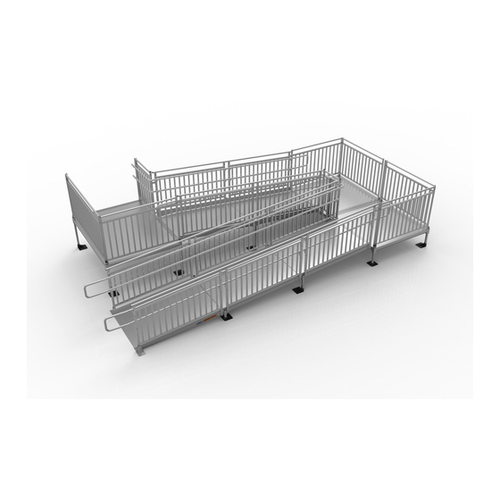
Assembly Manual
Image shown with multiple ramp and
platform rail options.
3-YEAR WARRANTY. Please register at www.ezaccess.com/warranty-satisfaction.
®
© EZ-ACCESS
, a division of Homecare Products, Inc. All rights reserved.
All text and images contained in this document are proprietary and may not be shared, modified, distributed,
reproduced, or reused without the express written permission of EZ-ACCESS.
Manufactured in the USA
17845 REV 05-29-18
Advertisement
Table of Contents

Related Manuals for EZ-ACCESS TITAN

Summary of Contents for EZ-ACCESS TITAN
- Page 1 , a division of Homecare Products, Inc. All rights reserved. All text and images contained in this document are proprietary and may not be shared, modified, distributed, reproduced, or reused without the express written permission of EZ-ACCESS. Manufactured in the USA...
- Page 2 ™ TITAN Code Compliant Modular Access System Assembly Manual ATTENTION INSTALLER and END USER Rated Load: 100 lbs. psf live load, 300 lbs. concentrated. DO NOT EXCEED RATED LOAD. Read this manual in its entirety, ensuring you understand all instructions and warnings prior to ramp assembly and use.
- Page 3 Read and follow all labels, instructions, and warnings prior to assembly and use. To obtain a copy of complete instructions and warnings, call customer service at 1-800-258-8503. Use caution at all times. Proper maintenance and upkeep to the TITAN™ Commercial Access System and all of its components is vital.
-
Page 4: Table Of Contents
TABLE OF CONTENTS SECTION 1: BASIC SYSTEM COMPONENTS BASIC SYSTEM COMPONENTS ......................... 5-9 SECTION 2: PLATFORMS INSTALL PLATFORMS ............................10 INSTALL SUPPORT TUBES AND FEET AND ADJUST PLATFORM HEIGHT ............11-12 CONNECT TWO PLATFORMS TOGETHER ....................12-13 INSTALL CROSS BRACE – PLATFORMS ....................... 14 CREATING DECKS FROM PLATFORMS ....................... -
Page 5: Section 1: Basic System Components
BASIC SYSTEM COMPONENTS Because each ramp configuration will differ from one another, your system may or may not contain all of these basic system components. Identify your system components before you begin. RAMPS AND RAMP HANDRAIL OPTIONS RAMP WITH TWO-LINE HANDRAILS RAMP WITH PICKETED GUARDS STARTER RAMP WITH TWO-LINE HANDRAILS* STARTER RAMP WITH PICKETED GUARDS*... - Page 6 KEY RAMP COMPONENTS TRHRLU – HANDRAIL END LOOP UPPER TRHRLL – HANDRAIL END LOOP LOWER END OF TUBE BENDS END OF TUBE BENDS TOWARD OTHER AWAY FROM OTHER END OF TUBE END OF TUBE TRHBPR – RAMP HANDRAIL END BRACKET (PAIR) TRRC –...
- Page 7 PLATFORMS AND PLATFORM HANDRAIL OPTIONS PLATFORM WITH TWO-LINE RAIL PLATFORM WITH TWO-LINE RAIL (STRAIGHT CONFIGURATION)* (TURN CONFIGURATION)* PLATFORM WITH PICKETED GUARDS PLATFORM WITH PICKETED GUARDS (STRAIGHT CONFIGURATION)* (TURN CONFIGURATION)* *FEET & LEGS SHOWN FOR CONTINUITY, NOT INCLUDED KEY PLATFORM COMPONENTS TCPCPR –...
- Page 8 CLOSURE OPTIONS TCTL5, TCTL6, TCTL7 TCG5, TCG6, TCG7, TCG654, TCG754 TWO-LINE RAIL CLOSURE PICKETED GUARD CLOSURE TTBCTL5, TTBCTL6 TTBCG5, TTBCG6, TTBCG554, TTBCG654 TURN BACK CLOSURE TWO-LINE RAIL TURN BACK CLOSURE PICKETED GUARD TCTCTL5, TCTCTL6 TCTCG5, TCTCG6, TCTCG554, TCTCG654 CORNER TURN CLOSURE TWO-LINE RAIL CORNER TURN CLOSURE PICKETED GUARD Page 8 of 77...
- Page 9 ADDITIONAL COMPONENTS FOR RAMPS & PLATFORMS TSLxxPR TXB36 & TXB736 – CROSS BRACE RAMP & PLATFORM SUPPORT LEGS WITH FEET (PAIR) TXB36 USED ON 5’ & XX DENOTES USABLE 6’ PLATFORM SIDES LENGTH (LENGTHS & RAMPS AVAILABLE 10” THROUGH 112") ...
-
Page 10: Section 2: Platforms
PLATFORMS 2.1. INSTALL PLATFORMS If your system does not include a platform, skip to ‘CONNECT RAMP SECTIONS’. Platform handrails are shown (FIGs. 2.1, 2.2, and 2.3) for clarity of how to orient platforms in various configurations. It is strongly suggested that all platforms and ramps be installed before installing handrails (see ‘HANDRAILS’... -
Page 11: Install Support Tubes And Feet And Adjust Platform Height
2.2. INSTALL SUPPORT LEGS AND FEET, THEN ADJUST PLATFORM HEIGHT 2.2.1. Support legs, plugs, and feet come in pairs. Support legs will come in lengths sufficient for the heights at specific locations. 2.2.2. Loosen all set screws in the platform corner pockets. 2.2.2.1 Set screws on the outside of the platform are for the platform support legs. -
Page 12: Connect Two Platforms Together
2.2.6. Lift each corner of the platform and install a foot on each support leg, oriented so that the foot extends under the platform (FIG. 2.4). The feet can be oriented in other directions if necessary due to site conditions but may present a tripping hazard if not oriented under the platform. - Page 13 FIG. 2.5 FIG. 2.6 Page 13 of 77...
-
Page 14: Install Cross Brace - Platforms
2.4. INSTALL CROSS BRACE For added stability, platforms with walking surfaces over 36″ high require bracing. The TXB36 CROSS BRACE is used for 5’ and 6’ platform sides and ramps. The TXB736 CROSS BRACE is used for 7’ platform sides. 2.4.1. -
Page 15: Creating Decks From Platforms
2.5. CREATING DECKS FROM PLATFORMS Decks can be created by combining platforms using TPPC (CONNECTORS – PLATFORM TO PLATFORM). Refer to SECTION 2.3, ‘CONNECT TWO PLATFORMS TOGETHER’. NEVER use two leg stubs at a platform connector; there must always be at least one leg with a foot reaching the ground in the connector. -
Page 16: Section 3: Ramps
RAMPS 3.1. CONNECT RAMP SECTIONS 3.1.1. Place the walking surface side of the ramp sections face down, onto cardboard or lawn so that the ramp is not scratched, dented, or damaged. 3.1.2. Butt the two sections together, end-to-end, ensuring there is no gap, then position the two center saddle brackets, included in the ), over the TRRC (CONNECTOR –... -
Page 17: Install Ramps On Platforms
3.2. INSTALL RAMPS ON PLATFORMS 3.2.1. The following will address attaching a ramp or ramp run to a platform. If the ramp needs to be angled with respect to the platform or is going to be attached to an existing porch, skip to ‘ANGLE RAMPS WITH RESPECT TO PLATFORMS, PORCHES, OR DECKS’... -
Page 18: Attach Support Legs To Ramps
3.3. ATTACH SUPPORT LEGS TO RAMPS 3.3.1. Install the support leg bracket, included in the TRRC (CONNECTOR – RAMP TO RAMP), on the center studs of the center saddle bracket with the round hole on the upper stud and the curved slot over the lower stud (FIG. 3.5). 3.3.2. - Page 19 3.3.4. Locate the appropriate TSLxxPR SUPPORT LEG PAIR (where “xx” denotes the leg length) for the location. Place a foot under the support leg bracket with the foot extending under the ramp, then insert a 1-1/2” support leg through the support leg bracket into the foot. Loosen the 3/8”-16 headless socket setscrews and the foot’s thumb screw if needed to fully engage the support leg in the foot (FIG.
- Page 20 3.3.9. Adjust the ramp support legs one at a time. Building codes and ADA guidelines call for a maximum slope of 1:12 (approximately 5°) and this is the required slope for the TITAN system. 3.3.9.1. Raise (or lower) the ramp sections at the center saddle bracket to take any sag out of the ramp run, then retighten the two set screws in each support leg bracket to 15 ft.-lbs.
-
Page 21: Install Cross Brace - Ramps
3.4. INSTALL CROSS BRACE - RAMPS If the ramp walking surface is over 36″ high, a TXB36 (CROSS BRACE) must be installed under the ramp (FIG. 3.10). 3.4.1. Separate ends of brace bands until they go around the support legs. 3.4.1.1. -
Page 22: Install A Single Ramp Or Ramp Run To An Existing Structure
3.5. INSTALL A SINGLE RAMP OR RAMP RUN TO AN EXISTING STRUCTURE If installing a ramp run to an existing landing other than a TITAN platform, such as a porch, deck, stairs, etc., follow these steps: Installing a ramp or ramp run to an existing structure requires a TRST (RAMP SUPPORT TOP) and a TTP48 or TTP54 (TRANSITION PLATE 48”... -
Page 23: Angle Ramps With Respect To Platforms, Porches, Or Decks
1”, regardless of the angle required (FIG. 3.12). 3.7.3. Anchor the transition top plate as described in SECTION 3.5. 3.7.4. Use the 1/4″ x 1” long self-drilling screw when attaching to a TITAN platform. FIG. 3.12 Page 23 of 77... -
Page 24: Section 4: Handrails
HANDRAILS 4.1. FRAMES 4.1.1. Two-line rails, picketed guards, and handrails are specific to the ramp length and provided in pairs when ordered with the ramp. The procedure for frame attachment is the same for the two-line rails and picketed guards. The procedure for installing handrails is explained in a later step. - Page 25 FIG. 4.1 FIG. 4.2 Page 25 of 77...
-
Page 26: Starter Frame
4.2. STARTER FRAME 4.2.1. The starter ramp (identifiable by its tapered section for transition to the ground) includes starter frames which are specific to the starter ramp, lower post supports, and 6’ handrails. The procedure for attaching starter frames is the same for both two-line rails and picketed guards. - Page 27 LOWER FRAME POST SUPPORT (RIGHT HAND SHOWN; LEFT HAND OPPOSITE) FIG. 4.3 FIG. 4.4 Page 27 of 77...
-
Page 28: Ramp Handrails
4.4. RAMP HANDRAILS 4.4.1. Ramp handrails are specific to the ramp length and provided in pairs when ordered with the ramp. The procedure for attaching ramp handrails is the same for the two-line rails and picketed guards. 4.4.2. One ramp handrail is required on each side of the ramp (handrails of the same length are interchangeable side-to-side). - Page 29 4.4.4.4. Slide the handrail connector into one end of the 1-1/2” diameter ramp handrail (FIG. 4.6). If handrail connector does not fit in the tube, use pliers to lightly compress handrail connector while sliding into 1-1/2” diameter top rail. 4.4.4.5. Slide the next ramp handrail over the handrail connector until fully engaged and align the adjustable handrail bracket tops.
-
Page 30: Field Convert Ramp Two-Line Rail To A Picketed Guard
4.5. FIELD CONVERT RAMP TWO-LINE RAIL TO A PICKETED GUARD 4.5.1. Remove the two-line rail frame from the ramp (if installed), then remove the midrail from the two-line rail frame (FIG. 4.8). 4.5.2. Install the ramp picketed guard into the two uppermost and lowermost holes in the frame using the provided 5/16”-18 x 2-1/4”... -
Page 31: Assemble Platform Two-Line Rails And Picketed Guards
4.6. ASSEMBLE PLATFORM TWO-LINE RAILS AND PICKETED GUARDS 4.6.1. Two-line rails and picketed guards are provided in pairs when ordered with the TITAN platform. Two-line rails can also be converted to picketed guards in the field, see SECTION 4.7. 4.6.2. Regardless of style, it is strongly recommended the bolts be assembled loosely (not fully tightened) until all have been installed and the handrail has been installed in the platform. - Page 32 4.6.5. For platform picketed guards, pre-assemble the top rail by inserting 5/16”-18 x 1” long hex bolts through a 5/16” flat washers, the uppermost hole in the angle posts, and into the 5/16”-18 round threaded inserts in the top rail. 4.6.6.
-
Page 33: Install Platform Two-Line Rails And Picketed Guards
4.7. INSTALL PLATFORM TWO-LINE RAILS AND PICKETED GUARDS 4.7.1. Platform two-line rails and picketed guards are installed in the same manner. Depending on the configuration, refer to FIGs. 4.11 and 4.12 as needed. 4.7.2. Pre-assemble the platform two-line rail or picketed guard for both sides of a straight configuration and the “first″... -
Page 34: Convert Two-Line Platform Handrails To Picketed Guards
4.7.6. Install 5/16”-18 x 1” long hex bolts through a 5/16” flat washer for the top rail, midrail, and angle post (do not use a flat washer on the lowermost holes). Tighten all fasteners securely (FIG. 4.12). 4.8. CONVERT TWO-LINE PLATFORM RAILS TO PICKETED GUARDS 4.8.1. -
Page 35: Section 5: Closures
CLOSURES Closures fill the space between ramp posts and platform posts. Like the ramp and platform handrails, they are available in two-line rails and picketed guards. The closures come with components which require the ramp to be mounted to one side or the other of a platform but the ramp can be centered or mounted in any location on a platform side using the two-line rail closure (refer to SECTION 5.3). - Page 36 FIG. 5.2 FIG. 5.3 Page 36 of 77...
- Page 37 5.3.4. Attach the barrier attachment plate to the barrier using a 5/16”-18 x 1” long hex bolt and 5/16” flat washer. Make sure the leg of the attachment plate with the two smaller holes is captured under the upper hook and in contact with the ramp side rail. Move the ramp or platform slightly if needed and clamp the attachment plate to the side rail, if possible, before drilling (FIG.
- Page 38 5.3.8. Referencing FIG. 5.6, locate a closure bracket. Remove the 5/16″-18 x 2-1/4″ hex bolt and 5/16” flat washer attaching the midrail of the Frame, then reinstall the bolt and washer through the slot in the short leg of the bracket, the Frame post, and back into the threaded insert in the midrail.
- Page 39 5.3.12. Insert 5/16”-18 square threaded inserts into both ends of the midrail. Use a rubber mallet or similar tool to fully seat the threaded inserts as needed (FIG. 5.8). 5.3.13. Install 5/16″-18 x 1″ hex bolts through a 5/16” flat washers, the long leg of the closure bracket, and the 2”...
-
Page 40: Two-Line Rail Top Rail
5.4. TWO-LINE RAIL TOP RAIL 5.4.1. Insert a 2-15/16” ring joiner in the Frame top rail and install an adjustable elbow with another 2-15/16” ring joiner as shown (FIGs. 5.9 and 5.10). 5.4.2. Assemble an adjustable elbow with threaded insert to the uppermost hole in the 2” x 2”... - Page 41 5.4.5. Loosen the elbow assembly screws and align the round faces of the adjustable elbows, then tighten the elbow assembly screws and joiner set screws enough to hold them in position (FIG. 5.11). 5.4.6. Measure the gap between the faces of the opposing rings of the 2-15/16” ring joiners (FIG.
-
Page 42: Picketed Guard Closure
5.5. PICKETED GUARD CLOSURE 5.5.1. Picketed Guard Closures are specific to the platform size (5’, 6’, or 7’) and require the ramp to be mounted to one side or the other of a platform. If the ramp is to be placed anywhere other than the side of a platform, custom components will be needed. - Page 43 5.5.3. Locate the appropriate barrier attachment plate. If the upper end of the ramp or ramp run terminates at a platform, use the “up sloping” version of the plate. If the lower end of a ramp or ramp run starts at a platform, use the “down sloping” version. Note the orientation of the larger 3/8”...
- Page 44 5.5.7. Locate a closure bracket and attach the short leg of the bracket to the Frame post with a 5/16″-18 x 2-1/4″ hex bolt, 5/16” flat washers, and 5/16″-18 nylon insert locknut oriented as shown (FIG. 5.15). Use the uppermost hole available or field drill at a higher location on the post if desired.
- Page 45 5.5.12. Measure the gap between the 1-1/2” square x 42-5/8” long closure post and the 2” x 2” angle post (FIG. 5.16). 5.5.13. Locate the 1-1/2” diameter round tube and cut to the length measured in the previous step. Using a metal file, remove any sharp edges left from cutting. 5.5.14.
-
Page 46: Closure Handrails
5.6. CLOSURE HANDRAILS Closure handrails are installed in the same manner for the Two-Line Rail and the Picketed Guard Closure. The images in this section show the installation using a Two-Line Rail closure. 5.6.1. Insert a 2-15/16” ring joiner in the Ramp Handrail and install a 1-1/2” diameter tube bend onto the other end of the joiner. - Page 47 FIG. 5.18 FIG. 5.19 Page 47 of 77...
-
Page 48: Two-Line Rail Turn Back Closure
5.7. TWO-LINE RAIL TURN BACK CLOSURE There are four special closures available for filling the space between two ramps in a turn back configuration: Two-Line Rail for a 5’ platform side; Picketed Guard for a 5’ platform side; Two-Line Rail for a 6’ platform side; Picketed Guard for a 6’ platform side. Turn back closures for a 7’... - Page 49 FIG. 5.21 5.7.3. The barrier is provided in the length needed for the platform side and should not need to be trimmed. Insert 1-1/2” square threaded inserts into both ends of the 1- 1/2” x 2” barrier. Use a rubber mallet to fully seat the insert if needed (FIG. 5.21). 5.7.4.
- Page 50 FIG. 5.22 FIG. 5.23 5.7.7. Place the assembly into the space between the ramp side rails. Make sure the legs of the barrier attachment plates with the two smaller holes are captured under the upper hooks and in contact with the ramp side rails. Move the ramps slightly if needed.
- Page 51 5.7.10. For the midrail, first measure the distance between the Frame posts at the turn back, then cut the 1-1/2” x 2” midrail to the measured length, less 5/8” to account for the threaded inserts and attachment plates, which will be installed in the following steps. 5.7.11.
- Page 52 5.7.15. Connect the Ramp Handrails at the turn back by first inserting 2-15/16” ring joiners in the open ends of the Ramp Handrails and adjustable elbows on the opposite end of the ring joiner. Then, install another 2-15/16” ring joiner into the other ends of the elbows.
- Page 53 5.7.17. Measure the gap between the faces of the opposing rings of the 2-15/16” ring joiners (FIG. 5.27). 5.7.18. Cut the 1-1/2″ diameter tube to the length measured. Using a metal file, smooth any sharp edges from cutting. 5.7.19. Install the cut 1-1/2″ diameter round tube between the 2-15/16” ring joiners. Remove and reinstall the adjustable elbows, if needed (FIG.
-
Page 54: Picketed Guard Turn Back Closure
5.8. PICKETED GUARD TURN BACK CLOSURE There are four special closures available for filling the space between two ramps in a turn back configuration: Two-Line Rail for a 5’ platform side; Picketed Guard for a 5’ platform side; Two- Line Rail for a 6’ platform side; Picketed Guard for a 6’ platform side. Turn back closures for a 7’ platform side are uncommon and are ordered as a custom closure. - Page 55 5.8.3. The 1-1/2” square x 42-5/8” long closure posts, barrier attachment plates, picketed guard closure spacer, and closure brackets are all installed at a guarded turn back in the same manner shown in the ‘PICKETED GUARD CLOSURE’ section (refer to 5.5.3 through 5.5.10 for assembling these components).
- Page 56 5.8.4. For the turn back top rail, first measure the distance between the 1-1/2” square x 42-5/8” long closure posts at the turn back, then cut the 1-1/2” diameter tube to the measured length, less 1/8” to account for the threaded inserts, which will be installed in the following steps.
- Page 57 5.8.8. Connect the Ramp Handrails at the turn back by first inserting 2-15/16” ring joiners in the open ends of the Ramp Handrails. Install a 1-1/2” diameter tube bend on the opposite end of the joiner. Orient the joiner set screws toward the underside of the ramp handrails (FIG.
- Page 58 FIG. 5.34 5.8.9. Locate the special turn back handrail and the 1-1/2” diameter x 9-5/8” long tube with two welded brackets. 5.8.10. Insert 2-15/16” ring joiners into both ends. Orient the joiner set screw toward the brackets on the underside and tighten the joiner set screws securely (FIG. 5.34). 5.8.11.
- Page 59 5.8.17. Attach the turn back handrail to both 2” X 2” turn back angle posts using 5/16”-18 x 1” long button head socket cap screws, 5/16”-18 nylon insert locknuts, and 5/16” flat washers (FIG. 5.35). 5.8.18. Tighten all ring joiner set screws fasteners securely. FIG.
-
Page 60: Two-Line Rail Corner Turn
5.9. TWO-LINE RAIL CORNER TURN There are four special closures available for filling the space between two ramps in a corner turn configuration: Two-Line Rail for a 5’ x 5’ platform; Picketed Guard for a 5’ x 5’ platform; Two-Line Rail for a 6’... - Page 61 5.9.3. Connect the Frame top rails at the corner turn by inserting 2-15/16” ring joiners in the open ends of the Frame top rails and adjustable elbows on the opposite end of the ring joiners. Install 2-15/16” ring joiners into the other ends of the elbows. Orient the joiner set screw toward the underside and the legs of the adjustable elbows, toward the 2”...
- Page 62 5.9.7. Adjust the Top Rail Standoff to contact the underside of the elbow, then use the holes in the standoff as a template to drill 5/16” or 11/32” holes through the 2” x 2” angle posts (FIG. 5.39). 5.9.8. Attach the Top Rail Standoff to the 2” X 2” angle posts using 5/16”-18 x 1” long button head socket cap screws, 5/16”-18 nylon insert locknuts, and 5/16”...
- Page 63 5.9.11. Connect the Ramp Handrails at the corner turn by first trimming one leg of two 1-1/2” diameter, 90° elbows. Trim the elbow leg which will be installed on the lower Ramp Handrail such that the leg pointing toward the 2” x 2” angle post in the corner is 2-1/2” (approximately) from the angle post.
- Page 64 FIG. 5.41 FIG. 5.42 Page 64 of 77...
- Page 65 FIG. 5.43 Page 65 of 77...
-
Page 66: Picketed Guard Corner Turn
5.10. PICKETED GUARD CORNER TURN There are four special closures available for filling the space between two ramps in a corner turn configuration: Two-Line Rail for a 5’ x 5’ platform; Picketed Guard for a 5’ x 5’ platform; Two-Line Rail for a 6’... -
Page 67: Section 6: Final Platform/Ramp Steps And Checks
FINAL PLATFORM/RAMP STEPS AND CHECKS 6.1. SECURE RAMPS TO PLATFORMS 6.1.1. Once positioning of all ramps and platforms, and installation of all handrails, connectors, and end loops are complete, you will need to secure ramps to platforms with Ramp End Clips (included in PRHP - RAMP HANGER PAIR). -
Page 68: Attach Frame Post To Platform Post
6.2. ATTACH FRAME POST TO PLATFORM POST 6.2.1. At all locations where a Frame post is not connected to a rail, picketed guard or closure component, it must be connected to a platform 2” x 2” angle post using a closure bracket (FIG. -
Page 69: Install Ramp Handrail End Loops
6.3. INSTALL RAMP HANDRAIL END LOOPS 6.3.1. The TITAN system may include both upper and lower end loops (FIG. 6.5). Install a Handrail End Loop in all locations where the handrail does not terminate in some other manner (for example, a return to a building or guard), including both Starter Ramp handrails. -
Page 70: Install Ramp Handrail End Loops With Lower (Child) Handrail
6.3.1.3. Install a 5/16”-18 x 2-1/2” long hex bolt through a flat washer, the frame post and into the threaded insert in the lower leg (FIG. 6.8). 6.3.1.4. Tighten all fasteners securely including the joiner set screw. FIG. 6.8 6.4. INSTALL RAMP HANDRAIL END LOOPS WITH LOWER (CHILD) HANDRAIL 6.4.1. -
Page 71: Install Platform Leg Inserts
6.4.1.3. Mark the lower leg of the end loop at the ring of the ring joiner in the lower handrail and trim the lower leg at the marked location. Remove the end loop to achieve a square cut (FIG. 6.10). 6.4.1.4. -
Page 72: Install Frame Top Rail End Plugs And Ramp Corner Protectors
6.6. INSTALL FRAME TOP RAIL END PLUGS AND RAMP CORNER PROTECTORS 6.6.1. Use 1-1/2” plastic end plugs on all open ends of the frame top rails (FIG. 6.12). Push them in by hand or use a rubber mallet. If necessary, use construction adhesive to bond the plug into the rail. -
Page 73: Final Checks
6.8.5. Check that all handrail ends are terminated with loops or returned to a guard or building. 6.8.6. Check that all Frame Top Rails are covered with end plugs and ramp side rails have corner protectors installed. 6.8.7. CONGRATULATIONS! The EZ-ACCESS® TITAN™ System is assembled. Page 73 of 77... -
Page 74: Section 7: Optional Equipment
OPTIONAL EQUIPMENT 7.1. RAMP SUPPORT 7.1.1. The TRST (RAMP SUPPORT) provides supplemental support at the upper or lower end of a ramp. When used, the TRST (RAMP SUPPORT) replaces the TRHBPR (RAMP HANDRAIL END BRACKET PAIR). 7.1.1.1. Attach the ramp supports with two each 5/16"-18 x 1-1/2" hex bolts and 5/16"... -
Page 75: Ramp Transition Plate
(with the TRST) instead of the TRHP (RAMP HANGER PAIR). It can also be used when transitioning from a TITAN ramp to an existing porch or deck, or when transitioning to the ground instead of the starter ramp in some situations. The ramp transition plate can be used at either end of a ramp or ramp run. -
Page 76: Section 8: Maintenance
MAINTENANCE 8.1. PERIODIC MAINTENANCE 8.1.1. Caution should be used at all times. Proper maintenance and upkeep to the ramp system is vital. 8.1.2. Periodically check the ramp for damage and tighten any loose fasteners to ensure safety. 8.1.3. At all times, keep the system clear of dirt, leaves, and other debris that may accumulate on the surface. - Page 77 ® Thank you for choosing EZ-ACCESS for your accessibility needs. We’d love to hear from you! 1-800-258-8503 www.ezaccess.com Page 77 of 77...
Need help?
Do you have a question about the TITAN and is the answer not in the manual?
Questions and answers