Table of Contents
Advertisement
Quick Links
Advertisement
Table of Contents

Summary of Contents for KTR NVT-E Series
- Page 1 KTR-N 42611 EN KTR Kupplungstechnik NVT-E Sheet: 1 of 27 GmbH Operating-/Assembly Instructions D-48407 Rheine Edition: NVT-E Operating-/Assembly Instructions Drawn: 11.10.12 Pz/Wy Replaced for: Please note protection mark ISO 16016. Verified: 19.11.12 Pz Replaced by:...
-
Page 2: Table Of Contents
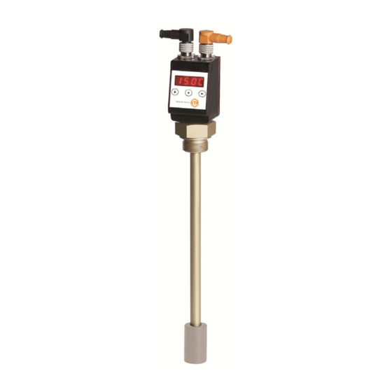
KTR-N 42611 EN KTR Kupplungstechnik NVT-E Sheet: 2 of 27 GmbH Operating-/Assembly Instructions D-48407 Rheine Edition: The series of level switches NVT-E is suitable for monitoring level and temperature in tanks in fluid systems. Depending on the model, the level switches are equipped with a different number of switching outputs. - Page 3 KTR-N 42611 EN KTR Kupplungstechnik NVT-E Sheet: 3 of 27 GmbH Operating-/Assembly Instructions D-48407 Rheine Edition: Table of Contents Analogue Outputs 4.8.1 Assignment of Upper Limit 4.8.2 Assignment of Lower Limit 4.8.3 Defining the Type of Signal 4.8.4 Testing the Analogue Output Diagnostics 4.9.1...
-
Page 4: Technical Data
KTR-N 42611 EN KTR Kupplungstechnik NVT-E Sheet: 4 of 27 GmbH Operating-/Assembly Instructions D-48407 Rheine Edition: 1 Technical Data Technical Data Operating pressure: Max. 1 bar Operating temperature: -20 °C to +80 °C Ambient temperature: -20 °C to +70 °C Weight: approx. -
Page 5: Hints
KTR-N 42611 EN KTR Kupplungstechnik NVT-E Sheet: 5 of 27 GmbH Operating-/Assembly Instructions D-48407 Rheine Edition: 2 Hints 2.1 General Hints Please read through these mounting instructions carefully before you set the level and temperature control into operation. The mounting instructions are part of your product. Please keep them carefully and close to the level and temperature control. -
Page 6: Assembly
KTR-N 42611 EN KTR Kupplungstechnik NVT-E Sheet: 6 of 27 GmbH Operating-/Assembly Instructions D-48407 Rheine Edition: 3 Assembly The level switches are supplied fully assembled and can be fixed to the tank by means of the thread. In this context please make sure that the float can move freely and sufficient distance to the tank walls and to other equipment is kept. -
Page 7: Led-Status Display
KTR-N 42611 EN KTR Kupplungstechnik NVT-E Sheet: 7 of 27 GmbH Operating-/Assembly Instructions D-48407 Rheine Edition: 4 Operation 4.2 LED-Status Display Light emitting diodes above the reading indicate the switching status of the outputs. The LEDs are assigned to the switching output numbered the same. -
Page 8: Key Lock Active
KTR-N 42611 EN KTR Kupplungstechnik NVT-E Sheet: 8 of 27 GmbH Operating-/Assembly Instructions D-48407 Rheine Edition: 4 Operation 4.3 Key Functions To select a menu item and set the values please proceed as follows: Open the main menu via the key . -
Page 9: Amendment Of Basic Settings
KTR-N 42611 EN KTR Kupplungstechnik NVT-E Sheet: 9 of 27 GmbH Operating-/Assembly Instructions D-48407 Rheine Edition: 4 Operation 4.5 Summary of Menu The different menu items are not displayed if the option is not available. Example: With a=0 the menu items for setting the analogue output are not available. -
Page 10: Defining Charging Level
KTR-N 42611 EN KTR Kupplungstechnik NVT-E Sheet: 10 of 27 GmbH Operating-/Assembly Instructions D-48407 Rheine Edition: 4 Operation 4.6 Amendment of Basic Settings 4.6.1 Defining Charging Level In this menu the displayed unit symbol for the charging level is defined. -
Page 11: Re-Assignment Of Switching Outputs
KTR-N 42611 EN KTR Kupplungstechnik NVT-E Sheet: 11 of 27 GmbH Operating-/Assembly Instructions D-48407 Rheine Edition: 4 Operation 4.6 Amendment of Basic Settings 4.6.3 Re-assignment of Switching Outputs The amendment of assignment of the switching outputs is described here based on the example of switching output 1. -
Page 12: Activating/Deactivating Key Lock
KTR-N 42611 EN KTR Kupplungstechnik NVT-E Sheet: 12 of 27 GmbH Operating-/Assembly Instructions D-48407 Rheine Edition: 4 Operation 4.6 Amendment of Basic Settings 4.6.5 Activating/Deactivating Key Lock To prevent unauthorized modifications of settings on the device, it is possible to activate a key lock. -
Page 13: Maximum Displayed Value Of Charging Level
KTR-N 42611 EN KTR Kupplungstechnik NVT-E Sheet: 13 of 27 GmbH Operating-/Assembly Instructions D-48407 Rheine Edition: 4 Operation 4.6 Amendment of Basic Settings 4.6.7 Maximum Displayed Value of Charging Level The displayed value (upper limit of the measurement range) for the maxium charging level is defined here. - Page 14 KTR-N 42611 EN KTR Kupplungstechnik NVT-E Sheet: 14 of 27 GmbH Operating-/Assembly Instructions D-48407 Rheine Edition: 4 Operation 4.6 Amendment of Basic Settings 4.6.10 Factory Settings Definitions of the factory settings set: Switching point / reset point x Delay for switching/delay for resetting for switching output x / x.
-
Page 15: Switching Outputs
KTR-N 42611 EN KTR Kupplungstechnik NVT-E Sheet: 15 of 27 GmbH Operating-/Assembly Instructions D-48407 Rheine Edition: 4 Operation 4.7 Switching Outputs All switching outputs are set in the same way. Therefore, the number of the switching output is marked x. Select... - Page 16 KTR-N 42611 EN KTR Kupplungstechnik NVT-E Sheet: 16 of 27 GmbH Operating-/Assembly Instructions D-48407 Rheine Edition: 4 Operation 4.7 Switching Outputs 4.7.1 Definition of Switching Characteristics Window function Function of make contact or break contact defining a signal window. If the measured window is reached, the output signal is set and deleted once it is left.
-
Page 17: Upper Switching Limit (Set Point)
KTR-N 42611 EN KTR Kupplungstechnik NVT-E Sheet: 17 of 27 GmbH Operating-/Assembly Instructions D-48407 Rheine Edition: 4 Operation 4.7 Switching Outputs 4.7.2 Upper Switching Limit (Set Point) The upper switching limit for switching output OUT 1 is set in the following submenu:... -
Page 18: Delay For Set Point
KTR-N 42611 EN KTR Kupplungstechnik NVT-E Sheet: 18 of 27 GmbH Operating-/Assembly Instructions D-48407 Rheine Edition: 4 Operation 4.7 Switching Outputs 4.7.4 Delay for Set Point The menu Extended functions x provides further settings for the switching output x. The submenu is located on the second submenu level: The delay time for set point and reset point prevents too many false alarms with turbulent conditions. -
Page 19: Testing The Switching Output
KTR-N 42611 EN KTR Kupplungstechnik NVT-E Sheet: 19 of 27 GmbH Operating-/Assembly Instructions D-48407 Rheine Edition: 4 Operation 4.7 Switching Outputs 4.7.6 Testing the Switching Output Testing the switching output can be started in the following menu: Testing options for the switching output... - Page 20 KTR-N 42611 EN KTR Kupplungstechnik NVT-E Sheet: 20 of 27 GmbH Operating-/Assembly Instructions D-48407 Rheine Edition: 4 Operation 4.7 Switching Outputs 4.7.7 Changing Display Function of Status LED The table shows an example with factory settings and with inverted status function for LED3.
- Page 21 KTR-N 42611 EN KTR Kupplungstechnik NVT-E Sheet: 21 of 27 GmbH Operating-/Assembly Instructions D-48407 Rheine Edition: 4 Operation 4.8 Analogue Outputs 4.8.1 Assignment of Upper Limit The assignment is defined as to which charging level is necessary to display the maximum analogue signal.
- Page 22 KTR-N 42611 EN KTR Kupplungstechnik NVT-E Sheet: 22 of 27 GmbH Operating-/Assembly Instructions D-48407 Rheine Edition: 4 Operation 4.8 Analogue Outputs 4.8.4 Testing the Analogue Output The analogue output can be tested, too. The highest, the average and the smallest analogue value can be displayed one after another.
- Page 23 KTR-N 42611 EN KTR Kupplungstechnik NVT-E Sheet: 23 of 27 GmbH Operating-/Assembly Instructions D-48407 Rheine Edition: 4 Operation 4.9 Diagnostics 4.9.1 Opening the Journal The last 6 incidents recorded of the switching output can be retrieved or deleted here. The journal entries are indicated in the following way: Example: ...
- Page 24 KTR-N 42611 EN KTR Kupplungstechnik NVT-E Sheet: 24 of 27 GmbH Operating-/Assembly Instructions D-48407 Rheine Edition: 4 Operation 4.9 Diagnostics 4.9.2 Maximum/Minimum Charging Level In this menu the maximum and minimum charging level saved is displayed or deleted. di A...
- Page 25 KTR-N 42611 EN KTR Kupplungstechnik NVT-E Sheet: 25 of 27 GmbH Operating-/Assembly Instructions D-48407 Rheine Edition: 4 Operation 4.9 Diagnostics 4.9.4 Assigning the Switching Output for Recording In this menu the switching output for recording is selected. Only one switching output can be recorded.
- Page 26 D-48407 Rheine Edition: 5 Spares Inventory, Customer Service Addresses Contact addresses of the KTR partners for spare parts and orders can be obtained from the KTR homepage under www.ktr.com. A T T E N T I O N ! KTR does not assume any liabilities or guarantees regarding the use of spare parts and accessories which are not provided by KTR and for the damages resulting herefrom.
- Page 27 KTR-N 42611 EN KTR Kupplungstechnik NVT-E Sheet: 27 of 27 GmbH Operating-/Assembly Instructions D-48407 Rheine Edition: 7 Maintenance and Service 7.1 Breakdowns, Causes and Elimination The breakdowns mentioned can only be indications for troubleshooting. For troubleshooting generally the adjacent components have to be included.
Need help?
Do you have a question about the NVT-E Series and is the answer not in the manual?
Questions and answers