Table of Contents
Advertisement
Advertisement
Table of Contents

Summary of Contents for Leguan L190
- Page 1 Operator and Service manual Edited: 13.12.2019...
-
Page 2: Table Of Contents
_________________________________________________________________________________ TABLE OF CONTENTS 1. INTRODUCTION AND WARRANTY CONDITIOS NTRODUCTION ARRANTY CONDITIONS 2. GENERAL INFORMATION ECHNICAL SPECIFICATIONS EACH DIAGRAM AND SUPPORT DIMENSIONS IGNS AND DECALS 3. SAFETY INSTRUCTIONS EFORE STARTING OPERATION ISK OF TIPPING OVER ISK OF FALLING ISK OF COLLISION ISK OF ELECTRIC SHOCK ISK OF EXPLOSION FIRE... - Page 3 _________________________________________________________________________________ OOM TRANSPORT POSITION MONITORING OVERRIDE 7. TRANSPORTATION 8. SERVICE, MAINTENANCE AND INSPECTION REGULATIONS ENERAL INSTRUCTIONS 9. SERVICE INSTRUCTIONS ERVICE AND CHECKS MAINTENANCE SCHEDULE 9.1.1 RAWLER TRACK SPROCKET NUTS USES REASING 9.3.1 REASING OF THE SLEW RING 9.3.2 REASING THE TELESCOPIC BOOM CHAIN PULLEY AND INSPECTION OF THE CHAIN 9.3.3 REASING OF ELESCOPING...
-
Page 4: Introduction And Warranty Conditios
1. INTRODUCTION AND WARRANTY CONDITIOS 1.1 Introduction LEGUAN LIFTS wants to thank you for purchasing this Leguan access platform. It is the result of Leguan’s long experience in design and manufacturing of access equipment. We ask you that you read and understand the contexts of this manual completely before operating the access platform. - Page 5 _________________________________________________________________________________ Warranty does not cover: Damages caused by wrong or negligent use of this product, or mischief. Any repairs or modifications to the product, performed without the prior authorization of the manufacturer. Damages caused by not following service and maintenance instructions. Adjustments, repairs and spare parts replacements caused by normal wear.
- Page 6 EN280:2015 FOLLOWING EUROPEAN HARMONIZED STANDARDS ARE USED WHEN THE MACHINERY WAS DESIGNED: EN280:2015 Teknisen tiedoston on valtuutettu kokoamaan: LEGUAN LIFTS OY Storage address of original documents: Ylötie 1, FI-33470 Ylöjärvi, Finland Ilmoitettu laitos / Notified Body INSPECTA TARKASTUS OY, NB0424 Testausraportti / Test Report No.
-
Page 7: General Information
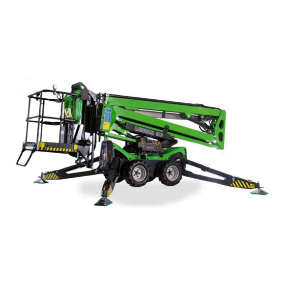
_________________________________________________________________________________ 2. GENERAL INFORMATION LEGUAN 190 is a self-propelled Mobile Elevating Work Platform – or commonly called access platform, designed for indoor and outdoor use. An access platform is destined for lifting of persons and their equipment only. It is not allowed to use an access platform as a crane. -
Page 8: Technical Specifications
_________________________________________________________________________________ 2.1 Technical specifications Working height 19,0 m Max. platform height 17,0 m Max. outreach @ 230 kg 8,1 m Max. outreach @ 120 kg 9,8 m Safe working load 230 kg Transport length 5,07 m Transport length without platform 4,32 m Transport height 2,11 m... -
Page 9: Reach Diagram And Support Dimensions
_________________________________________________________________________________ 2.2 Reach diagram and support dimensions Figure 2 Reach diagram Figure 3 Support dimensions... -
Page 10: Signs And Decals
4. General user instructions 13. Tie down points 5. Daily inspection 14. Tyre pressure 6. Always use outriggers 15. Leguan 190 decal 16. Lower controls’ decal 7. Control symbols decal 8. Emergency lowering (option) 17. Lift points 9. Residual current device... -
Page 11: Safety Instructions
_________________________________________________________________________________ 3. SAFETY INSTRUCTIONS The operator must know and follow all safety instructions. The operator must receive sufficient instructions in order to be able to use the lift correctly and safely. This Operators Manual must always be kept in the box on the platform. ATTENTION! In order to prevent unpermitted use of the access platform, take the ignition key that is located on ground level with you after ending operation. -
Page 12: Risk Of Tipping Over
In order to ensure the safe operation of this access platform the manufacturer has conducted approved tests for the LEGUAN 190 in accordance with the standard EN 280:2013+A1:2015 static stability test in accordance with paragraph 6.1.4.2.1 and dynamic overload test in accordance with paragraph 6.1.4.3 of the EN 280:2013+A1:2015. -
Page 13: Risk Of Collision
_________________________________________________________________________________ 3.4 Risk of collision Adjust the drive speed so that it is safe in regards to the ground conditions. The operator must follow all regulations concerning the use of safety equipment on the work site. Make sure that there are no overhead obstacles on the work site that could prohibit lifting of the platform, or objects that might cause a collision. -
Page 14: Daily Inspection Before Starting Operation
_________________________________________________________________________________ 3.7 Daily inspection before starting operation - Ground - Controls - Supports - Operating area - Horizontal levelling - Platform - Emergency stop button - Oil leakages - Emergency lowering - Working area ATTENTION! If you note faults or missing equipment on this access platform, do not put it into operation before the faults have been corrected. -
Page 15: Controls And Switches
_________________________________________________________________________________ 4. CONTROLS AND SWITCHES 4.1 Controls in platform The controls and indicators on the control panel at platform may be slightly different in different models. Indicators and switches that are marked as options are not mounted on all models. Figure 5: Upper control panel’s levers, switches and buttons 1. -
Page 16: Platform Overload Indicator Light
If the red fault light blinks, return booms onto their transport positions, perform daily inspection (0) and remove possible cause of the error. If the problem persists, contact your Leguan dealer. When a FAULT occurs, the red fault light will stay ON continuously. -
Page 17: Inclination Sensor Indicator Light
_________________________________________________________________________________ 4.1.4 Inclination sensor indicator light This access platform is equipped with inclination sensor which alerts when the inclination of the chassis exceeds the given limits. If the limits are exceeded while driving an orange indicator light will blink and give an audible alert can be heard. -
Page 18: Low Fuel Level Indicator
_________________________________________________________________________________ 4.1.7 Low fuel level indicator Low fuel level indicator light will be lit when there is approximately 4,5 liters of fuel left. This quantity will be enough for about 3 h of continuous working. Fuel tank capacity is 12,5 liters. When the low fuel indicator light is lit refuel as soon as possible (see 9.4). -
Page 19: Wireless Remote Control (Option)
_________________________________________________________________________________ 4.3 Wireless remote control (option) This access platform can be equipped with wireless remote control. The remote can be used to operate outriggers and drive functions. The remote, spare battery and a battery charger are located underneath the pedestal valve box. Figure 7: Remote storage 1. -
Page 20: Emergency Lowering Button At Ground Level (Option)
_________________________________________________________________________________ 4.4 Emergency lowering button at ground level (option) 1. Hour meter 2. Electric emergency lowering selection switch and button (1 boom, 2 boom, jib) (option) Figure 9: Emergency lowering at ground level 4.5 230 V connection and switches (option) 1. -
Page 21: Operation
_________________________________________________________________________________ 5. OPERATION An access platform is destined for lifting of persons and their equipment only. It is not allowed to use an access platform as a crane. It is the operator’s responsibility to understand and follow all operating and safety instructions. -
Page 22: Electric Motor
_________________________________________________________________________________ 5.1.2 Electric motor 1. Choose preferred control position (lower controls or platform controls) 2. Press electric motor start button, the button does not need to be held down. 3. Press start/stop button again to stop the motor. 5.2 Speed selection switch This access platform is equipped with three speed ranges. -
Page 23: Using The Crawler Track Chassis
_________________________________________________________________________________ 5.3.1 Using the crawler track chassis An access platform with skid steer chassis, equipped with crawler track chassis, offer many advantages compared with a machine on wheels. However, certain things regarding working and working environment must be taken into account with an access platform on tracks. In order to achieve the maximum life for the rubber tracks and crawler track chassis follow the instructions below. -
Page 24: Operation Of The Outriggers
_________________________________________________________________________________ 5.4 Operation of the outriggers The outriggers must be deployed and the chassis of the access platform must be levelled. The chassis can be leveled by either using automatic leveling function or controlling individual outriggers manually. The maximum allowed levelling inaccuracy is 1,0°. Make sure that the ground under every outrigger is solid enough –... -
Page 25: Operation Of The Booms
5.5.1 Automatic slewing stop function Leguan 190 has an automatic boom rotation (slewing) stop function when returning to transport position. The stop function is activated when the upper boom (2 boom) is lowered close to transport position and the telescope boom is pulled almost completely in. -
Page 26: Remote Control (Option)
_________________________________________________________________________________ 5.6 Remote control (option) Lower controls must be selected in order to operate the access platform remotely. 1. Select remote control with the remote control selection switch (Figure 6 (8)). 2. Lift remote control emergency stop button. 3. Start the remote (Figure 8 (3)). 4. -
Page 27: Emergency Lowering And Emergency Use
_________________________________________________________________________________ 6. EMERGENCY LOWERING AND EMERGENCY USE If the power supply for some reason cuts off (e.g. no fuel or electricity cuts off, or connecting cable fails) the booms can be lowered using the following methods. 6.1 Hand pump The access platform is equipped with a hand pump, which can be used to operate boom functions. Figure 11: Hand pump Using the hand pump: Stop the engine. -
Page 28: Outrigger Control Override
_________________________________________________________________________________ 6.3 Outrigger control override For possible emergency situations this access platform is equipped with outrigger monitoring override button (Figure 5 (20) or Figure 6 (9)), which allows the user to operate booms even the outriggers are not deployed properly. This function can be used for example in a situation where the jib boom needs to be lifted a little because of rough terrain or the platform has tilted backwards while extended storage. -
Page 29: Boom Transport Position Monitoring Override
_________________________________________________________________________________ 6.5 Boom transport position monitoring override For possible emergency situations this access platform is equipped with boom transport position override button (Figure 5 (20)). This feature allows the user to operate the outriggers and drive the access platform to a safe area in an emergency. The feature is meant to be used in a fault situation when one of the booms is not in transport position or if one of the transport position sensors and/or the boom angle/outreach sensor is faulty and prevents the operation of outriggers and drive. -
Page 30: Transportation
_________________________________________________________________________________ 7. TRANSPORTATION Before transportation lower the booms down to transport position and lift the outriggers completely up to transport position. NOTE! Transporting of this access platform is allowed in its transport position only. No persons or materials are allowed to be transported on the platform. All outriggers are equipped with lifting points (Figure 12) from which the access platform can be lifted if necessary. -
Page 31: Service, Maintenance And Inspection Regulations
Make sure that the access platform has been serviced according to the manual. Make sure that all inspections have been made according to local regulations. ATTENTION! All spare parts – especially electric components and sensors – must be original Leguan parts. -
Page 32: Service Instructions
_________________________________________________________________________________ 9. SERVICE INSTRUCTIONS 9.1 Service and checks, maintenance schedule Regarding the service of the engine see also engine manufacturer’s Operators Manual = CH = Check CL = Clean R = Replace A = Adjust F = First service at 50 h Operation month 100 h... -
Page 33: Crawler Track Sprocket Nuts
23*10.50-12 grass profile 3,0 bar (43 PSI) 23*10.50-12 TR profile 3,0 bar (43 PSI) Leguan TeHo trailer 6,0 bar (87 PSI) Do not exceed maximum inflation pressures marked on the tyres. Backlash of the wear pads on the telescopic boom must be checked every year and the wear pads must be replaced every 5 years. -
Page 34: Fuses
_________________________________________________________________________________ 9.2 Fuses The fuses of this access platform are located on the left side of the machine inside the electric box. 1. Fuses, voltage when ignition key switch is ON (lower or platform controls selected) 2. Fuses, constant voltage from battery 3. -
Page 35: Greasing
_________________________________________________________________________________ 9.3 Greasing Greasing of the machine is of utmost importance to prevent wear in joints. Most of the joints are service free - however the slewing ring must be greased in accordance with the maintenance schedule, using grease that contains EP (extreme pressure) additive. Outrigger bearings and articulation bearings in all hydraulic cylinders must be greased in accordance with the maintenance schedule. -
Page 36: Greasing Of Telescoping Booms
_________________________________________________________________________________ 9.3.3 Greasing of Telescoping Booms Glide surfaces of the telescoping booms (bottom surface, picture 18) should be greased with water resistant grease (e.g. Mobil XHP 222) during monthly greasing. The grease should be applied on the bottom surface of both middle boom and extension, on a surface area of approximately 30 mm wide measured from each side edge and for the whole visible length of the booms when the telescope is fully extended (picture 19). -
Page 37: Greasing Diagram
_________________________________________________________________________________ 9.3.5 Greasing diagram Figure 20: Greasing diagram... -
Page 38: Handling Of Fuel And Refueling
_________________________________________________________________________________ 9.4 Handling of fuel and refueling Check fuel level and refuel if necessary (fuel tank cap, 1). For Kubota engine use DIESEL fuel only. See engine manual. Use of other fuels is not allowed. Make sure not to let the fuel tank get empty. Should this happen, refuel and restart several times in 20 s intervals. -
Page 39: Hydraulic Oil Level
_________________________________________________________________________________ 9.6 Hydraulic oil level Hydraulic oil level can be checked with the dipstick in the filler cap (Figure 20 (1)). Oil level should be at the upper mark in the dipstick when the lift is in transport position (booms down on transport supports and outriggers completely up). -
Page 40: Water Level Check
_________________________________________________________________________________ 9.9 Water level check Correct position of the water level (on top of the control valve box at ground level) in relation to the upper surface of the slewing ring must be checked in accordance with the maintenance schedule, or if there is reason to believe that the position of the water level has changed: Make sure that the booms are in transport position and put a water level on the slewing ring. -
Page 41: Pedestal Valve Housing
_________________________________________________________________________________ 9.11 Pedestal valve housing Components inside the pedestal valve box: 1. Drive valves 2. Platform boom control valve solenoid K98 3. Lower controls boom solenoid K99 Figure 27: Pedestal valve housing All boom cylinders (except master levelling cylinder) are equipped with load control valves (1) which prevent boom movements in case e.g. -
Page 42: Overload Control Components
_________________________________________________________________________________ 9.12 Overload control components Overload control has been set to the correct values at the factory and it is strictly forbidden to change its settings. FALLING HAZARD! Overload control mechanism is located between the working platform and the platform support (Figure 27). -
Page 43: Boom Transport Support Sensors
_________________________________________________________________________________ 9.14 Boom transport support sensors The lower transport support sensor S10 is located in the rear side of the chassis behind a cover (Figure 30 (1)). When the 1 boom is on the transport support: Sensor face should face the narrowed section of the pin. The led lights in the sensor MUST NOT BE ON. - Page 44 _________________________________________________________________________________ The third sensor monitoring the transport position is the jib boom sensor (Figure 32). The sensor measures whether the jib boom is in transport position or not. The sensor is located at the tip of the telescope boom on the top surface. The sensor is adjusted like the two sensors before. When the jib boom is in transport position the sensor should be facing the notch on the boom.
-
Page 45: Safety Valve Test
_________________________________________________________________________________ 9.15 Safety valve test The safety valve of this access platform must be tested annually. Lifespan of the component is 30 years. After that the component must be replaced. When testing the component it is crucial to detach entire solenoid with the cable and the socket attached. -
Page 46: Battery Handling
If you find a fault, operation of the access platform must be stopped immediately and the hose or the component must be replaced. Contact Leguan service. -
Page 47: Repair Instructions
_________________________________________________________________________________ 10. REPAIR INSTRUCTIONS 10.1 Welding All load carrying steel parts are manufactured from S650MC (EN 10149-2) sheet, S420MC EN10149 sheet and S355J2H EN10219 tubular pipe. Welding repairs are only allowed to be carried out by professional welders. When welding, use only methods and additives suited for above mentioned steel qualities. -
Page 48: Instructions For Temporary Storage
_________________________________________________________________________________ 11. INSTRUCTIONS FOR TEMPORARY STORAGE The cable of the + pole of the battery should be disconnected, if the access platform is being stored for a period longer that one month. The access platform shall be covered and, if possible, stored inside or under a roof in a place where unauthorized persons don’t have access. -
Page 49: Trouble Shooting
_________________________________________________________________________________ 13. TROUBLE SHOOTING Following table shows eventual failures and malfunctions of the access platform and the ways how to repair them. ISSUE REASON CORRECTIVE ACTION Motor will not start when the Emergency stop button is Release all emergency stop start button is pressed. - Page 50 _________________________________________________________________________________ ISSUE REASON CORRECTIVE ACTION Electric motor stops suddenly Power failure. Lower the booms by using the during operation. emergency lowering. Check that there is current in mains. Emergency stop button is Release all emergency stop active. buttons. Electric motor thermal overload Wait for approx.
- Page 51 _________________________________________________________________________________ ISSUE REASON CORRECTIVE ACTION Outrigger gives in. Make sure that the ground Put extra support plates under doesn’t give in. the outriggers or move the machine to another place. Air in outrigger cylinder(s). Drive outriggers up and down a couple of times.
- Page 52 Motor will not start, fault light, Emergency stop button is active Release all emergency stop outreach light and overload light (telescope angle sensor buttons, contact Leguan service. defective). Overload signal light blinking. Load cell reading negative Make sure the platform sits (-50 kg or more).
-
Page 53: Performed Service
_________________________________________________________________________________ 14. PERFORMED SERVICE It is advisable to write down all service operations that are included in the periodical service. All services that have been made during the warranty period must be noted on the list below, otherwise the manufacturer’s warranty will void. The service operations mentioned in the maintenance schedule on chapter (see 9.1) shall be noted as follows: First Service (50 hours), 100 hour service, 200 hour / 1 Year service etc.
Need help?
Do you have a question about the L190 and is the answer not in the manual?
Questions and answers