
Related Manuals for Loudspeaker Kit M3


Summary of Contents for Loudspeaker Kit M3
- Page 1 M3 Assembly Instructions Designed and manufactured in Australia by The Loudspeaker Kit www.theloudspeakerkit.com Email: sales@theloudspeakerkit.com...
- Page 2 Assembly manual You will need: Phillips head screwdriver Woodworking glue Damp cloth Good quality masking tape Ratchet tie down strap (optional) Brick or other weight (optional) Preparation Lay the contents of the box out and check you have everything you need to complete the kit (see parts list on back page).
- Page 3 Assembly manual Lay out the rear, side, top and bottom panels as shown with mitres facing the work surface. Align carefully and arrange so that all panels are touching at the edges, with no gaps. This includes the ridge of the side panels Tape all four joints where the rear panel meets the side and top panels.
- Page 4 Assembly manual Lift the panels using the hole for the terminals, turning them over to the other side so the mitres are exposed. Apply a bead of wood working glue to the bottom of the mitre join.
- Page 5 Assembly manual Apply a second bead. Since the glue will tend to run down towards the bottom, it’s a good idea to apply the glue above half way up to ensure even coverage. Confirm the amount of glue applied by folding up the first panel. The glue should cover the entire surface in contact.
- Page 6 Assembly manual Apply a single larger bead of glue to the remaining sides on the top and bottom panels. Lift up the panels and hold together with pressure, securing them in position with masking tape. Apply the masking tape with firm pressure so that the panels are held together with moderate pressure.
- Page 7 Assembly manual Wipe off any excess glue with a damp cloth. Apply a thick glue bead around the internal surfaces of the mitres. You may prefer a zig zag pattern with a thinner bead. It’s a good idea to remove the panel and confirm even coverage. Note: the orientation of the front baffle is determined in the next step.
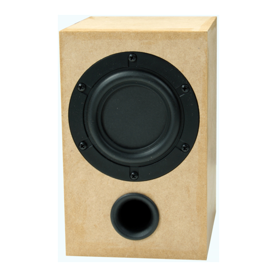
- Page 8 Assembly manual Baffle orientation The orientation of the front baffle relative to the terminals on the back is important. The port and speaker terminals are both located towards the bottom of the enclosure. Press the front baffle into place. The glue should ooze out around all joints.
- Page 9 Assembly manual Wipe off any excess glue at the join. Then apply tape with tension to firmly hold the baffle in place. Tape should first be applied perpendicular to the join. All joints should be covered. If pressure is applied when taping, no further clamping is required.
- Page 10 Assembly manual No ugly grille clips! Concealed neo magnets in the baffle and grille provide a minimalist front baffle. Our kits come with the magnets already installed for a quick and easy build. Drying time Typical wood glues can achieve moderate strength in as little as 30 minutes. If you are using PVA glue then a good indicator that it has set is the transparency.
-
Page 11: Installing Terminals
Assembly manual Installing terminals Push faston speaker connectors onto the speaker terminals. It’s often necessary to open out the connector slightly with a flat head screwdriver, since the fit is quite tight. Screw in the terminals with the wire loom already attached. Safe installation tip We recommend using a Phillips head screwdriver, as some powered drivers are more likely to cause damage if the head slips off the screw head. - Page 12 Assembly manual Before inserting the acoustic lining, cut an opening in the shape of a cross with a sharp blade. The cross should be centred 205mm from the top end. into the enclosure, the 125Now insert the black polyester acoustic lining.
- Page 13 Assembly manual Insert the lining, feeding the cable through the cross shaped cut out. The lining covers the top and rear internal walls of the enclosure, as shown in the sectional drawing below. You may choose to secure the lining in place with contact adhesive or a hot melt glue gun.
- Page 14 Assembly manual It’s now time to install the driver. Push the connectors onto the driver tabs. Correct polarity is important but this is made easy by using faston connectors that are sized to avoid mistakes. The larger negative connector goes to positive and the smaller negative connector goes to the other.
- Page 15 Assembly manual Screw the driver into place with a Phillips head screwdriver, securing the shaft with the other hand. Pushing the port into place completes the assembly. Your new kit is now ready to rock! Wire up the speaker to your amplifier and you‘re ready to rock!
-
Page 16: Grille Assembly
Assembly manual Grille assembly Lightly sand the grille frame so that the edges are slightly rounded over. This provides a more appealing effect when the grille fabric is in place. Shown below is the original grille prior to sanding (bottom) and then the grille after sanding (on top). Painting Although the grille frame will be covered with black cloth, it’s best to paint it black to ensure the lighter colour of the raw MDF won’t be seen. - Page 17 Assembly manual Lay out the grille on a suitable covering to protect your work surface. It’s a good idea to use disposable gloves for rolling the grille. The paint we use here is Acry-tech DuraTex which can be purchased through Cannon the Australian Distributor. The ideal roller has a 5mm short nap –...
- Page 18 Assembly manual Masking On the backside of the grille, you will notice a trench inset from the edges. This is the cut line and defines the area where the cloth will be glued to the frame. The area inside this line needs to be masked.
- Page 19 Assembly manual Glue is only required on the back surface as shown here – no glue is required to the sides. Allow a suitable setting time for the glue. This is different for each product. If you attempt to attach the cloth too soon, the results may be less than ideal. At this point, the advantage of using the mask becomes clear.
-
Page 20: Wrinkle Free Corners
Assembly manual Repeat with the other pair of sides. When the final end is pressed into place, all wrinkles should be removed. Always be careful to avoid contact between cloth and frame around the corners. Wrinkle free corners The biggest challenge in assembling a grille is the corners. If not done correctly, these will bunch up with many wrinkles. - Page 21 Assembly manual Now you can use your thumbnail to find the cut line. Pressing your nail into the trench, score all the way around. Then with a sharp blade, slowly and carefully cut away the grille cloth, using the trench as a guide. Tips for a better cut: ...
-
Page 22: Parts List
Assembly manual Parts List: 2 x 3” Full range drivers 2 x Round input Terminal 2 x Wire looms 14 x Panels of CNC machined MDF 20 x Screws 2 x 25mm Tuning Ports ...