Table of Contents
Advertisement
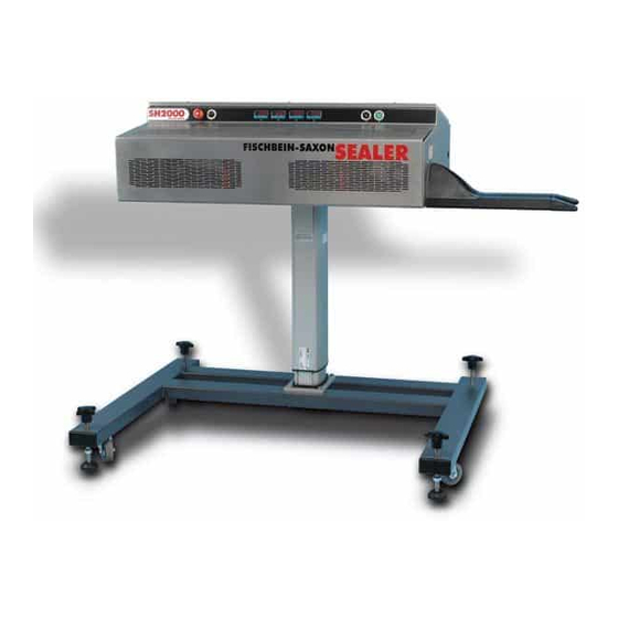
SH2000
HOT AIR CONTINUOUS HEAT SEALER
INSTRUCTION
AND
MAINTENANCE
MANUAL
FISCHBEIN-SAXON LTD
Incorporating The Thames Packaging Equipment Company and Fischbein Ltd
Alexandra Business Centre, 274 Alma Road, Enfield, Middlesex, EN3 7RS, England
Telephone: +44 (0) 844 3722 877
Fax: +44 (0) 844 3722 876
Manual No 82.150 Rev 100315
Advertisement
Table of Contents

Summary of Contents for FISCHBEIN Saxon SH 2000
- Page 1 INSTRUCTION MAINTENANCE MANUAL FISCHBEIN-SAXON LTD Incorporating The Thames Packaging Equipment Company and Fischbein Ltd Alexandra Business Centre, 274 Alma Road, Enfield, Middlesex, EN3 7RS, England Telephone: +44 (0) 844 3722 877 Fax: +44 (0) 844 3722 876 Manual No 82.150 Rev 100315...
- Page 2 F-94120 Fontenay-sous-Bois / Cedex France Phone: +33 1 48 77 15 34 Fax:: +33 1 48 77 26 41 Email: info@fischbein.fr GERMANY Fischbein Deutschland Gmbh Meisenstrasse 96 - D-33607 Bielefeld Deutschland Tel: +49 521 2997 212 Fax: +49 521 2997 213 Email: info@fischbein-online.de...
-
Page 3: Table Of Contents
SH2000 CONTENTS 1 SAFETY........................5 2 EXPERT MAINTENANCE..................7 2.1 Bag Sealer Handing..................9 3 DATA........................11 3.1 Speed Range & Capacity................11 3.2 Total Power Consumption ................11 3.3 Nett Weight ....................11 3.4 Voltage and Frequency ................11 3.5 Wiring ......................11 3.6 Environmental Conditions................11 3.7 Operating Temperatures................11 3.8 Relative Humidity ..................11 3.9 Thermocouples .....................11 3.10 PID Controllers....................11... - Page 4 SH2000 CONTENTS 9 PARTS and SPARES....................42 9.1 Mainframe Assembly..................42 9.1.1 Mainframe Assembly Parts List..............43 9.2 Bottom Plate RH Assembly................44 9.2.1 Bottom Plate RH Assembly Parts List............45 9.3 Bottom Plate LH Assembly.................46 9.3.1 Bottom Plate LH Assembly Parts List............47 9.4 Heater Assembly 240V..................48 9.5 Heater Assembly 115V..................49 9.6 Main Drive......................50 9.7 Mainframe Air Duct Assembly................51...
-
Page 5: Safety
Incorrect fitting or electrical wiring may lead to serious injury, loss of life and subsequent legal liability. Full Maintenance Contracts are available from Fischbein-Saxon Ltd SAFETY NOTICE IN THE INTEREST OF SAFETY THIS EQUIPMENT MUST BE ISOLATED FROM THE MAIN ELECTRICAL SUPPLY WHEN LEFT UNUSED AND UNATTENDED (i.e. - Page 6 SH2000 82.150 Rev 100315...
-
Page 7: Expert Maintenance
2 EXPERT MAINTENANCE QUALITY AT AN AFFORDABLE PRICE At Fischbein-Saxon we are aware of the critical role played by our machines in your production. We are also aware of how disruptive breakdowns can be and how costly in wasted time and lost production. - Page 8 SH2000 82.150 Rev 100315...
-
Page 9: Bag Sealer Handing
SH2000 HANDING 2.1 Bag Sealer Handing Right to Left Configuration Left to Right Configuration 82.150 Rev 100315... - Page 10 SH2000 82.150 Rev 100315...
-
Page 11: Data
Span and Zero adjustments are available, if required, via the PIDs menu system on ‘Level 3’ (further data available from Fischbein-Saxon Ltd if required). If PID calibration shows a serious inaccuracy it should be returned to Fischbein-Saxon Ltd. 82.150 Rev 100315... -
Page 12: Working Functions
SH2000 WORKING FUNCTIONS 4 WORKING FUNCTIONS The Sealer uses a patented system of hot air bag sealing which gives a high sealing efficiency together with reduced setting up and maintenance times. Sealer Infeed Guides & Infeed Belts Pressure Wheels Ploughs Heating Section Main Drive Feed Belts... -
Page 13: Controls
SH2000 CONTROLS 5 CONTROLS 5.1 Machine Controls Right to Left Control Panel Layout Left to Right Control Panel Layout PID 1 Emergency Stop PID 2 Column PID 3 (See note) Mode (Cool / OFF / Seal) PID 4 (See note)l On Switch Note: If only 2 PIDs are installed, PID 3 and PID 4 will be... -
Page 14: Switch Off
SH2000 CONTROLS 5.3 Switch Off Switch Mode (7) to “ ” – COOL DOWN 5.3.1 Machine will continue to run, but with the Carrying Belts running in reverse direction, until the PID Display indicates that the temperature has dropped to below 50°C. -
Page 15: Setting Up
SH2000 SETTING UP 6 SETTING UP A GOOD BAG SEAL IS OBTAINED BY THE VARIABLE INTERACTION OF THREE OPERATING FACTORS ON THE MACHINE: 1) Throughput SPEED (A) 2) TEMPERATURE (B) of the Sealing Air. 3) The HEIGHT (D) of the Heating Capsule Outlets (See Section 6.12). -
Page 16: Machine Positioning
SH2000 SETTING UP 6.2 Machine Positioning THE INFEED CENTRE LINE OF THE MACHINE MUST BE DIRECTLY IMPORTANT ABOVE AND PARALLEL WITH THE CENTRE LINE OF THE CONVEYOR 6.2.1 The machine must be correctly levelled on a sound base by four levelling screws S. 6.2.2 Height is adjustable by the electric column T. -
Page 17: Change Temperature
SH2000 SETTING UP 6.4 Change Temperature To prevent variations during production, temperature may have to IMPORTANT be autotuned. See AUTOTUNE section. 6.4.1 To check EXISTING TEMPERATURE in memory PRESS 6.4.2 To INCREASE working temperature PRESS 6.4.3 To DECREASE working temperature PRESS Any change of temperature will automatically set that temperature into current memory. -
Page 18: Pid Controller - General
SH2000 SETTING UP 6.5 PID Controller - General The PID Controller is a programmable unit giving cyclic monitoring and fine control of Sealing Air Temperature TEMPERATURE RANGE 0 - 400°C All controllers, whether fitted to new machines or supplied as replacement units, are preset to 150°C. -
Page 19: Pid Controller - Autotune
SH2000 SETTING UP 6.6 PID Controller - Autotune It is most important that the following sequence of instructions is IMPORTANT carried out in the CORRECT order. If an error is made in the following sequence, e.g. if the ▲ or ▼are not pressed simultaneously, or are mis-used in any way, the Controller will move into another non-related mode and display irrelevant data. - Page 20 SH2000 SETTING UP 6.6.7 RELEASE and then PRESS simultaneously 6.6.8 Display will alternate between The actual temperature will be seen to be falling at each display. 6.6.9 Allow temperature to fall to 50°C or less before proceeding with the next stage of AUTOTUNE.
-
Page 21: To Correct Any Setting Error
SH2000 SETTING UP 6.6.15 When AtSP is showing, press and HOLD for approximately 5 seconds This will alternate between: 6.6.16 Press and HOLD for approximately 5 seconds Display will alternate between tunE and degrees. This will be the actual temperature of the sealer. -
Page 22: Changing Bag Thickness
SH2000 SETTING UP 6.8 Changing Bag Thickness 6.8.1 Normal pressure wheel positions, as set up by the manufacturer, ensures that the wheels rest with a 0.25mm gap suitable for a middle range of bag material and thicknesses. 6.8.2 It is important that this clearance is regularly checked and maintained, otherwise undue wear on the pressure wheels may occur. -
Page 23: Adjustment To Pressure Wheels
SH2000 SETTING UP 6.9 Adjustment to Pressure Wheels Changing bag thickness may require some adjustment to the Pressure Wheels 6.9.1 Pressure Wheels are adjusted OUTWARDS for THICK BAGS 6.9.2 Pressure Wheels are adjusted INWARDS for THIN BAGS It is necessary to follow this procedure for each bag test run 6.9.3 SET PRESSURE HIGH ON THE ADJUSTER BEFORE MAKING ADJUSTEMNT by screwing C into B. -
Page 24: Adjusting Temperature For Bag Thickness
SH2000 SETTING UP 6.10 Adjusting Temperature for Bag Thickness Changing bag thickness may require some adjustment to the Temperature. A typical starting temperature is 150°C. A thicker bag may require a higher temperature. Run a test bag. If seal fails, increase temperature by 15°C and run again. THICK BAGS See note *. -
Page 25: Setting Heater Capsule Height
SH2000 SETTING UP 6.12 Setting Heater Capsule Height IMPORTANT: BEFORE UNDERTAKING ANY MAINTENANCE PROCEDURE, MACHINE MUST BE ISOLATED FROM MAINS SUPPLY. WARNING: THE HEATING CAPSULES MAY BE VERY HOT – ALLOW THEM TO COOL BEFORE CARRYING OUT THIS PROCEDURE 6.12.1 Unscrew the Height Adjustment Screws under the centre of each Heater Capsule (A) (access is under the Bottom Plates (C). -
Page 26: Change Machine Speed
SH2000 SETTING UP 6.13 Change Machine Speed The speed of the sealer is set by operating a rotary potentiometer. THIS OPERATION SHOULD BE CARRIED OUT BY AUTHORIZED PERSONNEL ONLY. 6.13.1.1 Remove the Rear cover. 6.13.1.2 Locate the speed control potentiometer (see Section 9.10). 6.13.1.3 Adjust to required speed. -
Page 27: Pressure Wheel Alignment
SH2000 SETTING UP 6.14 Pressure Wheel Alignment Touching at top Touching at bottom Moving Pressure Wheel Adjusting Screws Spacers Fixed Pressure Wheel 6.14.1 To check if the Pressure Wheels are in parallel alignment, look through the outfeed end of the sealer. 6.14.2 The faces of the Pressure Wheels must be parallel and at the same height (±0.5mm) 6.14.3 To adjust the height, remove the clips from the Pressure Wheel shafts and... -
Page 28: Bag Feed Guides
SH2000 SETTING UP 6.15 Bag Feed Guides The weight of the filled bag must be fully supported by the conveyor. Ensure that the bags are being fed straight and level. A Gearbox bracket B Brackets inside mainframe C Adjustment Nuts 6.15.1 Guide bars are vertically adjustable to suit a wide range of bag types. -
Page 29: Maintenance
SH2000 MAINTENANCE 7 MAINTENANCE IMPORTANT: BEFORE UNDERTAKING ANY MAINTENANCE PROCEDURE, MACHINE MUST BE ISOLATED FROM MAINS SUPPLY. 7.1 Removing Heating Capsule WARNING: THIS OPERATION MUST BE CARRIED OUT WITH MACHINE COLD 7.1.1 Disconnect the appropriate heater cable plugs (A). 7.1.2 Remove the thermocouple (D) from clip, noting which Heater Capsule(s) has the... -
Page 30: Replacing Heater Capsule - Heating Capsule 1
SH2000 MAINTENANCE 7.2 Replacing Heater Capsule - HEATING CAPSULE 1 THIS OPERATION MUST BE CARRIED OUT WITH MACHINE COLD Replacement of Heating Capsule is the reverse of instructions on previous page, but taking account of the following points: Note: Thermocouple(s) must be fitted to the capsules located in the position(s) where they were previously fitted. -
Page 31: Change Heater Module
SH2000 MAINTENANCE 7.3 Change Heater Module IMPORTANT: BEFORE UNDERTAKING ANY MAINTENANCE PROCEDURE, MACHINE MUST BE ISOLATED FROM MAINS SUPPLY. NOTE If machine is fitted with bag top support belts, it may be necessary to remove these first. 7.3.1 Remove rear cover. 7.3.2 Disconnect the heater plugs. -
Page 32: Replacing Carrying Belts
SH2000 MAINTENANCE 7.4 Replacing Carrying Belts 7.4.1 Pull back tensioner(s) (A) and remove pressure wheel drive belt(s) (B). 7.4.2 Remove the Belt Guards and slacken Nut (C) on the Carrying Belt Tension Wheel. 7.4.3 Note the position of the long screw (D) and slacken it about 5 turns. -
Page 33: Change Pressure Wheels
SH2000 MAINTENANCE 7.5 Change Pressure Wheels 7.5.1 Pull back tensioner(s) (A) and remove belt(s) (B). 7.5.2 Remove clip (C), washer, shims and spacer(s). 7.5.3 Lift off pressure wheel (D) and replace. 7.5.4 Re-assemble in reverse order. When re-assembled, there must be no vertical movement of the Pressure Wheel. -
Page 34: Replace Motor Or Gearbox
SH2000 MAINTENANCE 7.6 Replace Motor or Gearbox BEFORE UNDERTAKING ANY MAINTENANCE PROCEDURE, IMPORTANT MACHINE MUST BE ISOLATED FROM MAINS SUPPLY. Motor Gearbox bracket Motor fixing screws Gearbox & bracket fixings on outside face Coupling Gearbox Drive pulleys 7.6.1 Motor 7.6.1.1 Open rear cover. -
Page 35: Pid Controller Fault Diagnostic Procedure
SH2000 MAINTENANCE 7.7 PID Controller Fault Diagnostic Procedure The following failure conditions will be indicated by the controller’s display: 7.7.1 THERMOCOUPLE FAILURE 7.7.2 DISPLAY WILL ALTERNATE BETWEEN ACTION: Check thermocouple and its wiring and replace where necessary. 7.7.3 HEATER FAILURE Temperature reading remains at ambient level or lower than preset temperature. -
Page 36: Pid Controller Replacement Procedure
SH2000 MAINTENANCE 7.8 PID Controller Replacement Procedure IMPORTANT SOLATE FROM MAINS BEFORE CARRYING OUT THIS PROCEDURE 7.8.1 Switch OFF power to the machine and remove control box lid to provide access to controller. 7.8.2 Disconnect wiring from PID noting position of wires. 7.8.3 Release the panel clamps (C) on the body of the controller and withdraw the unit from the panel. -
Page 37: Routine Maintenance
SH2000 ROUTINE MAINTENANCE 8 ROUTINE MAINTENANCE BEFORE UNDERTAKING ANY MAINTENANCE PROCEDURE, IMPORTANT MACHINE MUST BE ISOLATED FROM MAINS SUPPLY 8.1 Daily As a daily routine, always check that the safety switch is functioning by opening the Front Cover with the machine running. IF THE MACHINE DOES NOT STOP AUTOMATICALLY, DO NOT CONTINUE TO OPERATE IT. -
Page 38: Weekly / 40 Hours
SH2000 ROUTINE MAINTENANCE 8.2 Weekly / 40 Hours ISOLATE THE MACHINE FROM THE ELECTRICITY SUPPLY IMPORTANT BEFORE CARRYING OUT MAINTENANCE Recommended WEEKLY checks comprise the following, plus the DAILY checks. Capsules removed to show pressure springs and carrying belts 8.2.1 Remove the Infeed Belt Guards, then remove any bag debris from underneath. -
Page 39: Monthly / 160 Hours
SH2000 ROUTINE MAINTENANCE 8.3 Monthly / 160 Hours ISOLATE THE MACHINE FROM THE ELECTRICITY SUPPLY IMPORTANT BEFORE CARRYING OUT MAINTENANCE. Recommended MONTHLY checks comprise the following, in addition to DAILY and WEEKLY checks. 8.3.1 Check Pressure Wheels and adjust as necessary. 8.3.2 Check tightness of all screws in drive chain. -
Page 40: Yearly / 2000 Hours
SH2000 ROUTINE MAINTENANCE 8.4 Yearly / 2000 Hours ISOLATE THE MACHINE FROM THE ELECTRICITY SUPPLY BEFORE IMPORTANT CARRYING OUT MAINTENANCE. Before starting the following checks and service, remove the HEATING ASSEMBLIES - BOTTOM PLATES, AND GEAR BOX. Place on the work bench. 8.4.1 PRESSURE ADJUSTER 8.4.1.1... - Page 41 SH2000 ROUTINE MAINTENANCE NOTES 82.150 Rev 100315...
-
Page 42: Parts And Spares
SH2000 PARTS AND SPARES 9 PARTS and SPARES 9.1 Mainframe Assembly 82.150 Rev 100315... -
Page 43: Mainframe Assembly Parts List
SH2000 PARTS / SPARES 9.1.1 Mainframe Assembly Parts List 82.150 Rev 100315... -
Page 44: Bottom Plate Rh Assembly
SH2000 PARTS / SPARES 9.2 Bottom Plate RH Assembly 82.150 Rev 100315... -
Page 45: Bottom Plate Rh Assembly Parts List
SH2000 PARTS / SPARES 9.2.1 Bottom Plate RH Assembly Parts List 82.150 Rev 100315... -
Page 46: Bottom Plate Lh Assembly
SH2000 PARTS / SPARES 9.3 Bottom Plate LH Assembly 82.150 Rev 100315... -
Page 47: Bottom Plate Lh Assembly Parts List
SH2000 PARTS / SPARES 9.3.1 Bottom Plate LH Assembly Parts List 82.150 Rev 100315... -
Page 48: Heater Assembly 240V
SH2000 PARTS / SPARES 9.4 Heater Assembly 240V 82.150 Rev 100315... -
Page 49: Heater Assembly 115V
SH2000 PARTS / SPARES 9.5 Heater Assembly 115V 82.150 Rev 100315... -
Page 50: Main Drive
SH2000 PARTS / SPARES 9.6 Main Drive 2 11 Item Part No Description 12.200 Motor 65.1.296 M5x20 Skt Cap Screw 73.023 Coupling 71.012 Drive Pulley 71.012 SS Drive Pulley 71.027 Grearbox Bracket LH 71.028 Grearbox Bracket RH 65.1.95 M6x15 Button Head Screw 65.1.163 M4x10 Button Head Screw See table below... -
Page 51: Mainframe Air Duct Assembly
SH2000 PARTS / SPARES 9.7 Mainframe Air Duct Assembly 82.150 Rev 100315... -
Page 52: Bag Guide
SH2000 PARTS / SPARES 9.8 Bag Guide Item Part No Description Quantity – Gearbox Bracket – – Bracket inside Mainframe – 73.030 Bag Guide 65.3.157 M6 Nuts 82.150 Rev 100315... -
Page 53: Control Panel
SH2000 PARTS / SPARES 9.9 Control Panel Right to Left Control Panel Layout Left to Right Control Panel Layout Item Part No Description 27.913.6 PID 1 27.913.6 PID 2 27.913.6 PID 3 (See note) 27.913.6 PID 4 (See note) 27.809 E Stop 27.802 Column Switch (if fitted) -
Page 54: Rear Housing
SH2000 PARTS / SPARES 9.10 Rear Housing Note: This shows the Left to Right configuration. For the Right to Left configuration of the Control Panel switches and PIDs, see Section 9.9. Item Part No Description Quantity 27.714 Power Supply 27.707 Inverter –... -
Page 55: Recommended Spares List
SH2000 PARTS / SPARES 9.11 Recommended Spares List 9.11.1 6-12 Months Routine Maintenance Part No Description Quantity 50.93 Belt, Drive 67.421.5 Thermocouple 71.106.3 Heating Capsule RH (240V) 71.106.4 Heating Capsule LH (240V) 67.908.3 Solid State Relay 27.913.6 PID Controller (Programmed) 71.091.1 Pressure Plate 50.47... -
Page 56: Electrical Schematic
SH2000 PARTS / SPARES 9.12 Electrical Schematic For wiring diagram use K2K2M000. 9.13 Safely Disposing of a FSL Sealer If the sealer becomes damaged beyond repair, or simply worn to a non-functional state after years of service, it should be put out of service only after it is safe to dispose of it. -
Page 57: Machine Layouts
SH2000 MACHINE LAYOUTS 10 MACHINE LAYOUTS 10.1 Head Unit - Right to Left Feed 82.150 Rev 100315... -
Page 58: Pedestal Unit With Extension Arm - Right To Left Feed
SH2000 MACHINE LAYOUTS 10.2 Pedestal Unit with Extension Arm - Right to Left Feed 82.150 Rev 100315... -
Page 59: 2000 Series Trolley Unit
SH2000 MACHINE LAYOUTS 10.3 2000 Series Trolley Unit 82.150 Rev 100315... -
Page 60: Annex Section 7. Plug And Socket Assembly
SH2000 ANNEX Section 7 Annex Section 7. Plug and Socket Assembly 82.150 Rev 100315... - Page 61 SH2000 ANNEX Section 7 82.150 Rev 100315...
- Page 62 SH2000 ANNEX Section 7 82.150 Rev 100315...
- Page 63 SH2000 ANNEX Section 7 82.150 Rev 100315...
- Page 64 SH2000 ANNEX Section 7 82.150 Rev 100315...
- Page 65 SH2000 ANNEX Section 7 82.150 Rev 100315...
- Page 66 SH2000 ANNEX Section 7 82.150 Rev 100315...
- Page 67 SH2000 ANNEX Section 7 82.150 Rev 100315...
- Page 68 SH2000 ANNEX Section 7 82.150 Rev 100315...
- Page 69 SH2000 ANNEX Section 7 82.150 Rev 100315...
Need help?
Do you have a question about the Saxon SH 2000 and is the answer not in the manual?
Questions and answers