Table of Contents
Advertisement
Quick Links
Advertisement
Table of Contents

Summary of Contents for DOGA SCOUT II
- Page 1 Instructions manual / Electric screwdrivers SCOUT II INSTRUCTIONS MANUAL...
- Page 2 Instructions manual / Electric screwdrivers The tool delivered with this manual may been modified for specific needs. In that case, please give us the tool code number written on our shipping note or the appoximate tool delivery date when you will place an order for a new similar tool or for spare parts. In that way, you will be sure to get the required and/or spare part.
- Page 3 Instructions manual / Electric screwdrivers...
-
Page 4: Table Of Contents
11.1.2 Communication control letter..........................p.35 11.1.3 Command................................. p.36 11.1.4 Check sum (BBC)............................. p.36 11.2 Parameter change and save..........................p.36 11.3 Monitoring data output............................p.37 12. PC communication software, SCOUT II-Manager (for MS Windows)………………………..…………………… p.38 12.1 Software install……………………………………………………………………………………………………………. p.38 12.2 How to use………………………………………………………………………………………………………………… p.38... -
Page 5: Specification
Program share - Only one(1) XS-38D with the version lower than v4.3 can be connected to Scout II 2. Main features of SCOUT II - Maximum 5 screwdrivers can share one program of Scout ( 4 of XS-38D v4.3 or XS-40D through A,B,C,D port + 1 extra... -
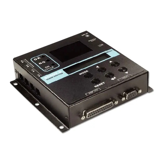
Page 6: Lay Out
Instructions manual / Electric screwdrivers 3. LAY OUT... -
Page 7: Caution
If the screwdriver port "A" is empty (not used), then external power (24VDC, 1A) is required. 2) Scout II have 4 screwdriver ports for direct connecting of XS-38D and XS -40D. Also one extra screwdriver can be connected through 25P I/O. -
Page 8: Accessories ( Option Items )
Instructions manual / Electric screwdrivers 5. Accessories ( Option items ) -
Page 9: Operation
Instructions manual / Electric screwdrivers 6. Operation 6.1 Mode By pressing the MODE button, it circulates Work, Log-in, Parameter and Measuring mode. Work means operating. Before parameter mode, password is required. Every setting is possible in Parameter mode. Once logged in, it circulates Work, Parameter and Measuring mode, until the power is off and on again. -
Page 10: Work Mode
Instructions manual / Electric screwdrivers 6.2 Work mode 6.3 Log-in mode... -
Page 11: Parameter Mode
Instructions manual / Electric screwdrivers 6.4 Parameter mode... -
Page 12: Measuring Mod
Instructions manual / Electric screwdrivers 6.5 Measuring mode... -
Page 13: Program # And Parameters
Instructions manual / Electric screwdrivers 6.6 Program # and parameters The program numbers from 1 to 8 are effected together with parameters 1~8 for number of screws, P9~16 for minimum tightening time, P17~24 for maximum tightening time, and P38~45 tear mid count number. -
Page 14: Parameters
Instructions manual / Electric screwdrivers 6.7 Parameters Name Specification Default P01-P08 Program # Save total number of screws on P1-8 Minimum screw tightening time P09-P16 Minimum tightening time Input : 0.000 - 9.999 sec ( "0" : No use ) Maximum screw tightening time P17-P24 Maximum tightening time... - Page 15 Instructions manual / Electric screwdrivers Name Specification Default Select one of followings 0 : Not use Fastening buzzer 1 : OK only 2 : NG only 3 : OK + NG Select one of followings 0 : Not use Cycle buzzer 1 : OK only 2 : NG only 3 : OK + NG...
- Page 16 Instructions manual / Electric screwdrivers Driver is locked between Cycle complete and Auto system Lock next new Cycle start signal. 0 : Disable 1 : Enable Count number display on the panel Count UP Enable 0 : Disable ( Count DOWN ) 1 : Enable ( Count UP ) Time limit on auto cycle start makes NG Timer setting on...
-
Page 17: Interface
Instructions manual / Electric screwdrivers 7. Interface 7.1 25P I/O interface details The configuration of 25P I/O port for remote control is as below. PIN no. Configuration IN / OUT External Motor Run signal External Torque Up signal Cycle Start Cycle Stop Cycle Reset Driver Lock... -
Page 18: Input (Negative(-) Common Wiring)
Instructions manual / Electric screwdrivers 7.2 INPUT (Negative(-) Common wiring) -
Page 19: Input (Positive(+) Common Wiring)
Instructions manual / Electric screwdrivers 7.3 INPUT (Positive(+) Common wiring) -
Page 20: Output (Negative(-) Common Wiring)
Instructions manual / Electric screwdrivers 7.4 OUTPUT (Negative(-) Common wiring) -
Page 21: Output (Positive(+) Common Wiring)
Instructions manual / Electric screwdrivers 7.5 OUTPUT (Positive(+) Common wiring) -
Page 22: Binary Coding For Program Selecting By 3 Pins ( Pin No. 8,9 And 10 ) - P35 Enable
Instructions manual / Electric screwdrivers 7.6 Binary coding for Program selecting by 3 pins ( Pin no. 8,9 and 10 ) - P35 Enable Program no. pin 10 (PS3) pin 9 (PS2) pin 8 (PS1) ** Program selecting is not effective during the cycle ON. -
Page 23: Wiring Example #1 - Tower Lamp, Solenoid Valve, Sensors, Switch
Instructions manual / Electric screwdrivers 7.7 Wiring example #1 - Tower lamp, solenoid valve, sensors, switch... -
Page 24: Wiring Example #2 - Inter-Lock Of Two Screwdriver With Mid-Count Signal Setting
Instructions manual / Electric screwdrivers 7.8 Wiring example #2 - Inter-Lock of two screwdriver with Mid-Count signal setting... - Page 25 Instructions manual / Electric screwdrivers...
-
Page 26: Connecting To Hybrid Hdc Controller
Instructions manual / Electric screwdrivers 7.9 Connecting to Hybrid HDC controller The screw count number on P74 of Hybrid HDC controller can be changed by program selecting on Scout II through the RS-232 interface port. The only RS-232 (not USB) interface of HDC controller works with Scout II. -
Page 27: Timing Chart
Instructions manual / Electric screwdrivers 8. Timing Chart ( example ) number of fastening screw is supposed to be three(3) -
Page 28: Timing Chart Details For Ng / Ok Set Up
Instructions manual / Electric screwdrivers 9. Timing chart details for NG / OK set up 9.1 Fastening OK 9.2 Fastening ERROR 1 - TIME LAPSE... -
Page 29: Fastening Error 2 - Time Over
Instructions manual / Electric screwdrivers 9.3 Fastening ERROR 2 - TIME OVER 9.4 Fastening ERROR 3 - NO TORQUE UP ( Most common mistake in assembly ) -
Page 30: Cycle Start / Stop In The Various Operating Conditions
Instructions manual / Electric screwdrivers 10. Cycle Start / Stop in the various operating conditions 10.1 Auto Start Where fastening number count is not necessary It starts to count the number of fastening automatically just after cycle ends with "0" display of counter, and repeats without any cycle start and stop signal for counting. -
Page 31: Start (Pulse) + Stop By Time Limit (Optional)
Instructions manual / Electric screwdrivers Example) the target screw number is "10" 10.3 Start (pulse) + Stop by time limit (Optional) Automatic flow assembly line with pallet conveyor system which is controlled by PLC The SCOUT cooperates with PLC for the signals of cycle start and cycle stop, in order to move the work-piece to next process automatically. - Page 32 Instructions manual / Electric screwdrivers If the time is limited on P27 and the fastening is not complete until the set time, Scout will verify the fastening NG at the set time. It can be cleared to the target by pressing RESET button. Example #1 ) Cycle start pulse signal with time limit on P27 Example #2 ) Cycle start pulse signal without...
-
Page 33: Start (Pulse) + Stop (Pulse)
Instructions manual / Electric screwdrivers 10.4 Start (pulse) + Stop (pulse) - Semi-auto flow assembly line with belt conveyor system - Scout gives the alert buzzer when the work-piece moves out to the next process before the cycle is completed. It has two signals for work-piece coming IN and OUT using the optical or magnetic sensors. -
Page 34: Rs-232C & Usb Communication Port
Instructions manual / Electric screwdrivers 11. RS-232C & USB communication port Scout II provides both RS-232C and USB communication port together with free PC software, SCOUT II Manager. The com port and cable specification is as below. - Page 35 Instructions manual / Electric screwdrivers...
- Page 36 Instructions manual / Electric screwdrivers...
- Page 37 Instructions manual / Electric screwdrivers...
-
Page 38: Pc Communication Software, Scout Ii-Manager (For Ms Windows)
PC communication software, SCOUT II-Manager, is easy to program screw counter. The Min, max fastening time & total number of screws can be changed on PC software and downloaded to Scout II. For changing parameters of SCOUT II by PC software, it requires Log-in password. - Page 39 Instructions manual / Electric screwdrivers...
- Page 40 Instructions manual / Electric screwdrivers...
Need help?
Do you have a question about the SCOUT II and is the answer not in the manual?
Questions and answers