Table of Contents
Advertisement
Quick Links
333 Bayview Avenue Amityville, New York 11701
For Sales and Repairs, (800) 645-9445
For Technical Service, (800) 645-9440 or visit us at
http://tech.napcosecurity.com/
(Note: Technical Service is for security professionals only)
Publicly traded on NASDAQ
Symbol: NSSC
© NAPCO 2019
OVERVIEW
™
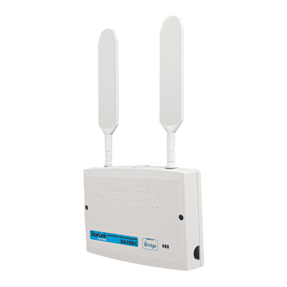
The StarLink
Connect models SLE-LTEV-C and SLE-
LTEV-Z are multi-function Commercial Burglary and Resi-
dential Fire alarm radio communicators and supervised sys-
tem interface modules. They provide several options to the
home owner:
1. A monitoring path to a central station through a digital
LTE (Verizon) radio and optionally through a TCP/IP
network to the Internet using a hardwired Ethernet con-
nection or optional Wi-Fi adapter (Wi-Fi not used for
Commercial Burglary);
2. Notification alerts of alarm system changes to a mobile
device. Notifications use iBridge Messenger SMS text
messaging and/or emails to inform the user and/or deal-
er of system state changes. For this release, these noti-
fications are enabled in the iBridge Connected Home
Services website at http://ibridge.napconoc2.com;
NAPCO control panels are programmed in the tradition-
al way using PCD-Windows Quickloader software. The
StarLink Connect application is available on the en-
closed CD or can be downloaded from the Napco Tech-
nical Library at http://tech.napcosecurity.com/.
3. Allows users to control Z-WAVE devices in several
ways:
a. Through the use of a mobile device app;
b. Through Z-Wave Schedules;
c. Through Z-Wave Scenes;
If required, mount the unit to a single-, dual-, or three-gang
electrical box and route the wires through the back knock-
out(s), or as specified by local codes. See WI2140 for pro-
gramming instructions (all manuals are available for
download at http://tech.napcosecurity.com/).
StarLink SLE Series radios use proprietary data-capture
technology that captures the alarm report from the control
panel and transmits the alarm signals to the SLE Control
Center (the Napco "NOC"); the alarm signals are then for-
warded to ANY central station via Contact ID or 4/2 via
DACT from the NOC or Sur-Gard System II, Sur-Gard Sys-
tem V, Bosch D6100IPV6 or Bosch D6600 Receiver (with
ITS-D6686 Ethernet Adapter) via TCP/IP using standard
line security. The SLE Control Center reports a trouble sig-
nal in the event that the network does not receive the ex-
pected supervision signal from the wireless communicator.
In addition, both StarLink radio models can be powered di-
rectly from the control panel.
The StarLink radio model names are as follows:
SLE-LTEV-C - Network Compatible LTE (Verizon) alarm
capture radio communicator, SIM card included. White
plastic enclosure.
StarLink™ Connect SLE-LTEV-C / SLE-LTEV-Z Alarm Communicators -- Installation Instructions
™
StarLink
Connect LTE Series
SLE-LTEV-C / SLE-LTEV-Z
Multi-Function Alarm Communicators
INSTALLATION INSTRUCTIONS
SLE-LTEV-Z - Network Compatible LTE
(Verizon) alarm capture radio communi-
cator, SIM card included. Includes the
SLE-ZWAVE-MOD
White plastic enclosure.
For Commercial Burglary installations, under the armed con-
dition, any loss of communication must be treated as a Bur-
glary Alarm at the Central Station.
ADDITIONAL COMPONENTS
In addition to the models listed above, the following sub-
assemblies are available:
SLE-WIFI-MODULE - Allows your Napco iBridge
™
Link
device to connect to the Internet by means of a
wireless (Wi-Fi) link, eliminating a wired Ethernet cable
connection.
SLE-ZWAVE-MOD - Included with the SLE-LTEV-Z radio,
the Z-Wave module (PC board) allows your Napco
®
iBridge
or StarLink
devices.
SLE-DLCBL - Download Cable, 6 feet.
SLE-ANTEXT30 - Extended antenna with 30 feet of cable.
SLE-ANTEXT50 - Extended antenna with 50 feet of cable.
SLE-ANTEXT75 - Extended antenna with 75 feet of cable.
(Any suitable external cellular antenna is permitted by
UL). Always follow the manufacturer's installation in-
structions. Note: Antennas are not Listed by UL.
SPECIFICATIONS
The following specifications apply to all StarLink radio mod-
els unless otherwise stated:
Electrical Ratings for +12V (both models powered by the
control panel)
Input Voltage: 10-15VDC (regulated power-limited output
from control panel). Do NOT connect to full-wave recti-
fied (FWR) power.
Input Current:
SLE-LTEV-C standby current: 126mA (135mA with
telco EOLR)
For Z-Wave add 10mA; for Wi-Fi add 45mA
SLE-LTEV-Z standby current: 135mA (145mA with
telco EOLR)
Transmission current (both models): Add 135mA.
AGENCY LISTINGS
UL 1610 Standard For Central-Station Burglar-Alarm Units
UL 985 Standard For Household Fire Warning System Units
LTEV models are Verizon
WI2307CLF 6/19
Z-Wave
module.
™
device to connect to your Z-Wave
Network Certified
®
®
or Star-
1
Advertisement
Table of Contents

Subscribe to Our Youtube Channel
Summary of Contents for NAPCO StarLink Connect LTE Series
- Page 1 Z-Wave StarLink Connect application is available on the en- devices. closed CD or can be downloaded from the Napco Tech- SLE-DLCBL - Download Cable, 6 feet. nical Library at http://tech.napcosecurity.com/. SLE-ANTEXT30 - Extended antenna with 30 feet of cable.
- Page 2 PC board. Operation is as follows: TB5: PGM3 (–): Open collector output. This output is normally open collector / high. Use the Napco "NOC" Normal Standby Condition: to configure options for PGM activation.
- Page 3 ty; requires a restart (full power down and full power up sequence) to restore operation. RED DIAGNOSTIC LED Labeled "D7", this LED is located in the middle of the PC board. One blink indicates a weak or non-existent signal DL: RED DIAGNOSTIC LED from the network (green LED is off).
- Page 4 DSC or Honey- should spend as much time as needed to obtain the well control panel (when connected to a NAPCO control highest signal level possible. panel, both LEDs remain off). The LED labeled "D44" is a.
- Page 5 (input) to annunciate the trouble (activate a trouble between the equipment and receiver; 3. Connect the equip- sounder) when an open is detected. With Napco control ment into an outlet on a circuit different from that to which panels, program a dedicated zone for Day Zone, Mini- the receiver is connected;...
- Page 6 (program the radio to report all troubles on Wiring Fault Report" feature located in the Advanced PGM1). Features screen of the Napco " NOC" (at http:// You can also wire to the positive terminal of the dedicated NapcoNoc2.com).
- Page 7 STARLINK RADIO RELATED EVENT JUMPER DESCRIPTIONS REPORT CODES (Contact ID by default) Jumper block labeled "X5"; from top to bottom, as detailed in the following table. Note: Contact ID is CONTACT ID PULSE always available in response to a Contact ID EVENT AREA CODE...
- Page 8 DEDICATED TO GPRS POWER". 10K EOLR required when TIP/RING Wiring SUPERVISION Fault Report is enabled in the Napco "NOC". For optional local line fault annunciation, enable the Telco Line Cut Monitor feature in the control panel programming. Note: All end-of-line...
Need help?
Do you have a question about the StarLink Connect LTE Series and is the answer not in the manual?
Questions and answers