Table of Contents

Related Manuals for Hunter Loki


Summary of Contents for Hunter Loki
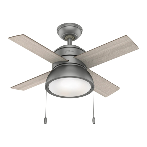
- Page 1 Loki Installation Manual Model: 51039 Matte Silver 51040 Brushed Nickel 51042 Antique Copper 59385 Fresh White 59386 Polished Nickel 59387 Noble Bronze Fan weight ±2 lbs: 17.6 lbs (8.0 kg) ©2020 Hunter Fan Co. PG3693 r052720...
- Page 2 - All wiring must be in accordance with national and local electrical codes ANSI/NFPA 70. If you are unfamiliar with wiring, use a qualified electrician. c.2 - Use only Hunter replacement parts. This equipment has been tested and found to comply with the limits for a Class B digital device, pursuant to part 15 of the FCC Rules. These limits are designed to provide reasonable protection against harmful interference in a residential installation.
- Page 3 We recommend that you pull everything out of the box and lay it out. We have grouped the drawn components below with the hardware you’ll need for those Hunter Pro Tip: parts. The screws below are drawn to scale to make it easier to identify what piece of hardware is needed to install each component.
-
Page 4: Choosing The Right Installation Location
A little more information on Angled Mounting: For optimum performance and appearance, a longer downrod should be used with your Hunter ceiling fan when installing on high or angled ceiling. If your ceiling is angled greater than 34° you will also need an Angled Mounting Kit. -
Page 5: Installing The Ceiling Bracket
You have two options for installation. Pick which one works best for your location. Remove any existing Hunter Pro Tip: bracket prior to installation. Only use the provided Hunter ceiling bracket that came in your fan’s box. The machine screws are the ones that came with your outlet box. -
Page 6: Hanging The Fan
1886 Hanging the Fan NOTICE To prevent damage to fan, ALWAYS lift holding either the fan housing or the downrod. Place the downrod ball into the slot in the ceiling bracket. Progress Check: Your fan should look like this. Note: Fan style may vary. -
Page 7: Wiring The Fan
If you are unfamiliar with wiring or uncomfortable doing it yourself, please contact a qualified electrician. You are going to need these: Hunter Pro Tip: Here is how to connect the wires: 4 Wire Nuts (these are in the... -
Page 8: Installing The Canopy
1886 Installing the Canopy Insert the two canopy screws found in the hardware bag. Canopy Screw Lift the canopy into place so that the screw holes are aligned. Installing the Blades: Attach each blade to a blade iron using the grommets, found in the hardware bag, and the shoulder screws, found in the hardware bag. -
Page 9: Assembling The Light Kit
1886 Assembling the LIght Kit 2 of 3 Light Kit Screw Feed the 9-pin plug connector coming Partially install two light kit assembly from the bottom of the motor housing screws, found in the hardware Align the keyhole slots in the top of the light kit through the center hole in the light kit bag, halfway into the motor housing assembly with the partially installed assembly... - Page 10 1886 Installing the Pull Chains The fan pull chain controls the speed: from high to off. The light pull chain controls the light fixture: on and off. Remove and discard the plastic connectors from the ends of the short pull chain. Attach the pull chain pendants to the light and fan pull chains.
-
Page 11: Troubleshooting
Hunter instructions, accidental damage caused by the fan owner or related parties, Please do not ship your fan or any fan parts to Hunter. Delivery will be refused. modifications to the fan, improper or incorrectly performed maintenance or repair,... - Page 12 1886 Downrod If you need a different downrod length follow these steps: Follow steps 1-5 to remove standard downrod pipe Follow steps 6-10 to reassemble with new downrod WARNING FAN FALL HAZARD To prevent SERIOUS INJURY or DEATH: • ALWAYS follow the downrod assembly instructions exactly.
Need help?
Do you have a question about the Loki and is the answer not in the manual?
Questions and answers