Oakley 5U Modular Series Builder's Manual
Voltage controlled phaser
Hide thumbs
Also See for 5U Oakley Modular Series:
- Builder's manual (33 pages) ,
- User manual (11 pages) ,
- Builder's manual (15 pages)

Subscribe to Our Youtube Channel
Related Manuals for Oakley 5U Oakley Modular Series


Summary of Contents for Oakley 5U Oakley Modular Series
- Page 1 Oakley Sound Systems 5U Oakley Modular Series MOSPhaser Voltage Controlled Phaser PCB Issue 1 Builder's Guide V1.5 Tony Allgood Oakley Sound Systems CARLISLE United Kingdom...
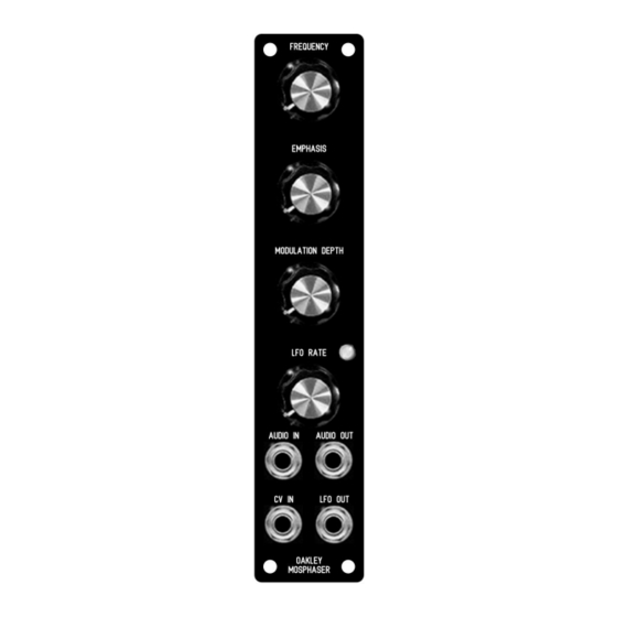
- Page 2 The 1U wide panel design for the MOSPhaser for MOTM format systems. The fpd file for this panel can be found on the project webpage.
- Page 3 Introduction This is the Project Builder's Guide for the issue 1 MOSPhaser 5U module from Oakley Sound. This document contains a basic introduction to the board, a full parts list for the components needed to populate the boards, and a list of the various interconnections.
- Page 4 The MOSPhaser PCB This is the issue 1 Oakley MOSPhaser behind a natural finish Schaeffer panel. Note the use of the optional Sock4 socket board to facilitate the wiring up of the sockets. I have provided space for the four main control pots on the PCB. If you use the specified 16mm Alpha pots and matching brackets, the PCB can be held firmly to the panel without any additional mounting procedures.
- Page 5 Issue 1 MOSPhaser Parts List For general information regarding where to get parts and suggested part numbers please see my useful Parts Guide at the project webpage or http://www.oakleysound.com/parts.pdf. The components are grouped into values, the order of the component names is of no particular consequence.
- Page 6 Trimmer 100K trimmer (eg. Bourns 3386F) TUNE Potentiometers All pots Alpha 16mm PCB mounted types. 10K linear or reverse log FEEDBACK 50K linear FREQUENCY, MOD_DEPTH 50K log LFO_RATE Three 16mm pot brackets. Capacitors 100nF axial multilayer ceramic C20, C7, C3, C16, C22, C12, C14, C10, C6, C5, C1, 100pF 2.5mm C0G ceramic 470pF 2.5mm C0G ceramic C13, C8, C4...
- Page 7 IC sockets are not necessary but I would advise using a 16-pin DIL socket for U4. Miscellaneous Leaded axial ferrite beads L1, L2 MTA156 4 way header – Oakley/MOTM power supply MTA100 6-way header – Synthesizers.com power supply Molex/MTA 0.1” header 8-way – for connecting to sockets Molex/MTA 0.1”...
- Page 8 Connections Power connections – MOTM and Oakley The PSU power socket is 0.156” Molex/MTA 4-way header. Friction lock types are recommended. This system is compatible with MOTM systems. Power Pin number +15V Module GND Earth/PAN -15V Pin 1 on the I/O header has been provided to allow the ground tags of the jack sockets to be connected to the power supply ground without using the module’s 0V supply.
- Page 9 Building the MOSPhaser module using the Sock4 board This is the simplest way of connecting all the sockets to the main board. The Sock4 board should be populated in the way described in our construction guide found on the project webpage.
- Page 10 Hand wiring the sockets If you have bought Switchcraft 112A sockets you will see that they have three connections. One is the earth or ground tag. One is the signal tag which will be connected to the tip of the jack plug when it is inserted.
- Page 11 Wiring the LED The Oakley MOSPhaser has one LED which is held in place on the panel with a LED lens and clip. These are wired to the main board in similar fashion to other Oakley 5U modules. Using a two way Molex KK housing to connect the bi-colour LED to the circuit board. The LED is held onto the panel with a clear Cliplite lens, or equivalent.
- Page 12 Testing Apply power to the unit making sure you are applying the power correctly. Check that no device is running hot. Any sign of smoke or strange smells turn off the power immediately and recheck the polarity of the power supply, and the direction of the ICs in their sockets and the polarity of the electrolytic capacitors.
- Page 13 Calibration Apply power to module and allow to warm up for a few minutes. Turn the Frequency and modulation controls to their minimum positions. Measure the voltage across zener diode D3 – which is to the right of U4, the 4009UBE. Adjust the trimmer labelled TUNE so that the voltage across D3 reads 0.75V.
- Page 14 The Low Frequency Oscillator Output The internal LFO circuit produces a triangle wave output of approximately +/-5V which is also available from a dedicated front panel socket. This allows you to use the MOSPhaser's internal LFO for other modulation purposes. The LFO's output signal is automatically routed to the modulation depth pot when no jack is inserted in the CV input.
-
Page 15: Final Comments
Oakley modules. If you can't get your project to work and you are in the EU, then Oakley Sound Systems are able to offer a 'get you working' service. If you wish to take up this service please e-mail me, Tony Allgood, at my contact e-mail address found on the website.
Need help?
Do you have a question about the 5U Oakley Modular Series and is the answer not in the manual?
Questions and answers