
Related Manuals for Soluna S12 EU-A50

Summary of Contents for Soluna S12 EU-A50
- Page 1 Installation Manual Battery Energy Storage System Soluna S12 EU-A50 DLG Energy (Shanghai) Co., Ltd. June 2020 Version V1.1 Page 1 of 60...
- Page 2 About this manual This manual describes how to install the SOLUNA Battery Energy Storage System (referred to as BESS from hereon), the Soluna S12 EU-A50, manufactured by DLG Energy (Shanghai) Co., Ltd. Please read this manual before you attempt to install the product, and follow the instructions throughout the installation process.
-
Page 3: Table Of Contents
Step 7 : .......................... 34 How to operate Soluna S12 EU-A50 ..................36 Turn on or turn off the Soluna S12 EU system .............. 36 How to operate the LCD ....................37 The LCD is operated by touch, to view the information in the LCD simply touch to view the details.......................... -
Page 4: Safety Precautions
Safety precautions A Soluna BESS is designed and tested following relevant international safety standards. As an electrical and electronic device, all applicable safety regulations must apply during installation, operation, and maintenance. Incorrect use or misuse may result in: • Injury to the life and personal safety of the operator or other people. -
Page 5: Warning Signs
Warning signs Warning signs are used to warn you about the conditions that may cause severe injury or damage to the device. They instruct you to exercise caution to prevent danger. The following table describes the warning signs used in this manual. Sign Name Description... -
Page 6: Safety Guide
Safety guide After receiving this product, first, confirm the product package is intact. If any question, contact the logistic company or local distributor immediately. The installation and operation of the system must be carried out by professional technicians. They have received professional training, and thoroughly familiar with all the contents in this manual and the safety requirements of the electrical system. -
Page 7: Transportation And Installation
Transportation and installation • Keep the package and unit complete, dry and clean during storage and transportation. • Please remove and install it with at least two people. • To ensure the safe operation of the BESS and avoid personal injury, please select proper handling and installation tools, and take mechanical protection measures to PPE, such as wearing steel toe capped shoes, overalls and so on. -
Page 8: Grid-Tied Operation
What to do at the battery end of life • Do not dispose of the system together with household waste. The user is responsible and obliged to send it to a designated organization for recycling and disposal. Seek advice from Soluna Australia, Page 8 of 60... -
Page 9: Product Introduction
Product Introduction Soluna’s S12 EU-A50 can connect with a solar power generation system, assisting the customer to use environmentally-friendly energy 24 hours per day. The BESS can store the energy generated by the PV, using it when required, reducing electricity bills, improving the household energy self-consumption and working when there is a BLACKOUT. -
Page 10: Outline Dimensions
Outline Dimensions Figure 2.1 outline dimension Width Depth Height 1335 Weight Page 10 of 60... -
Page 11: Functional Description
Functional description The basic principle of Soluna S12 EU-A50 Figure2.2 basic principle of Soluna S12 EU Page 11 of 60... -
Page 12: Working Modes
Working modes Soluna’s S12 EU-A50 have the working modes (see below): Mode 1: In the daytime, the PV power will charge the battery as a priority, if the battery is full, the PV power is used to power the loads, then finally excess energy is sold to the Grid. -
Page 13: Active Power And Reactive Power Setting
Active power and reactive power setting The Soluna BESS is capable of producing reactive power and feeding it into grid through the setting. Feeding in management can be controlled directly by the grid company through a dedicated communication port. Volt-Var Response Mode The Soluna BESS series complies with AS/NZS 4777.2: 2015 standard which introduced the... - Page 14 Volt-Watt Response Mode The Soluna BESS series complies with AS/NZS 4777.2: 2015 standard. The grid voltage at which the inverter output starts to drop/de-rate is set to 250 V by default as required by the standard. This means that when the grid voltage exceeds 250 V, the maximum output of the inverters will be restricted (as required by the standard).
- Page 15 Remark: User can find the QV & VM icon in reset & advanced setting icon on the LCD), Please find the following picture for details. DRMs, logic interface for AS/NZS 4777.2:2015, is used to receive and response commands from grid company and then adjust inverter output power. The Earth fault alarm Before the inverter starts to connect to the grid, the inverter will first detect the impedance of PV + to ground, and the impedance of PV- to ground.
-
Page 16: Technical Data
Technical Data Technical data of System PV input Max. recommended DC power (W) 6500 Max. DC voltage (V) 500V Isc PV (absolute Max.) (A) 16A/16A Number of MPPT trackers Strings per MPPT tracker Nominal DC operating voltage (V) Max. input current (A) 11A/11A MPPT voltage range (V)... -
Page 17: Technical Data Of The Battery Module
Forced airflow Ingress protection IP20 Condition Indoor conditioned Certificates IEC62109 CE-LVD EN 62477-1: 2012+ALL: 2014 Warranty Please refer to SOLUNA WARRANTY CONDITIONS Technical Data of the battery module Physical Characteristics Width 205 mm Depth 678 mm Height 436 mm Weight... - Page 18 Altitude Max. 2,000 m Cooling Strategy Natural Convection Reliability & Certification Certificates Cell: UL1642 Battery Module: IEC62619 / UL1973 Hazardous Materials Classification Class 9 Transportation UN38.3 Ingress Rating IP20 Warranty Please refer to SOLUNA WARRANTY CONDITIONS Page 18 of 60...
-
Page 19: Appearance
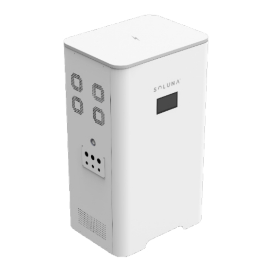
Appearance ① ② Figure 2.3 Appearance Number Name Remark ① Soluna brand ② LCD panel Page 19 of 60... - Page 20 Page 20 of 60...
- Page 21 Figure 2.5 Appearance Number Name Remark ① The door lock of the system ② The door key Page 21 of 60...
-
Page 22: Installation
Installation Installation tools Page 22 of 60... -
Page 23: Spacing During Installation And Operation
Position Min spacing Remark Side spacing 100cm There needs to be a clearance of 100cm on either side of the Soluna BESS Backspacing 10cm It needs to be installed against the wall Note: For detailed requirements about the narrowest maintenance channel, escape route, etc. -
Page 24: Wiring Specifications
Store the idled system in its original packaging, and take anti-moisture and anti-dust measures. After removing the system from the box, check the following items: Item Name Remark Soluna System Case Battery module PV connector PV connector removal tool Wrench 3# M8*100 Expansion screws... -
Page 25: Basic Installation Requirement
Basic installation requirement The BESS cabinet is IP20 and suitable for installation in dry, dusty environments. According to EMC standards, the BESS cabinet is designed to meet the installation requirements in a home environment. Select the installation site according to the following criteria: •... -
Page 26: Installation Procedures
Installation procedures The mechanical installation steps are as follows: Step 1 Remove the S12 EU-A50 casing and the battery modules from the packaging box Figure 3.1 battery module & system case Number Name Remark ① System case ② Battery modules... -
Page 27: Step 2
Step 2: The casing is attached to a wall: Figure 3. Attached the casing to the wall Number Name Remark ① Wall ② Soluna System ③ Expansion Screw ④ Fixed Bracket ⑤ Ground Page 27 of 60... -
Page 28: Step 3
Step 3 Open the door of Soluna system, and open the case of the battery module Figure 3.4 Battery Unit Number Name Remark ① System case ② Case of Battery module Page 28 of 60... -
Page 29: Step 4
Step 4: Push the battery module into the system, and lock the battery cable and plug in the CAN communication & Remote line. Figure 3.6 RJ45 terminal Number Name Remark ① Remote wire ② Battery cable ③ CAN communication line Remark: Connecting wire for communication line 1) All CAN1 lines are parallel for the internal communication of battery units 2) All CAN2 lines are parallel for the external communication. -
Page 30: Step 5
Step 5 Fixed battery module and close the door of the BESS. Figure 3.7 Fixed battery module Number Name Remark ① M6*12 Combination screw ② Fixed bracket Page 30 of 60... -
Page 31: Step 6
Step 6 External circuit connection (PV\GRID\LOAD) Figure 3.8 External circuit connection Number Name Remark ① Emergency Stop ② Load connector ③ Grid connector ④ GEN connector ⑤ PV connector ⑥ GEN control port Page 31 of 60... - Page 32 Only qualified PV strings under the local electrical safety laws and regulations and comply with the technical parameters of this manual are allowed to connect to the Soluna S12 EU-A50. The PV string connected to the BESS must adopt the DC connector configured for the BESS. Do not use other connection devices without authorization from our company;...
- Page 33 Only qualified AC transmission cables under the local electrical safety laws and regulations and comply with the technical parameters of this manual are allowed to connect to the Soluna S 1 2 E U - A 5 0 Recommended wire specifications for safe system operation are as shown in the following table.
-
Page 34: Step 7
Step 7 : Electrical connection A. The following diagram is an example for the Australia, South Africa and New Zealand grid systems. Please see Figure A for details. Note: In Australia, the neutral cable of the On-Grid side and Back-Up side must be connected, otherwise Back-Up function will not work. - Page 35 Figure C Remark: Although the RCD is shown the Soluna system itself has the function of leakage protection, therefore the RCD is a suggestion, not a requirement, the RCD provides an extra layer of protection. If installing an RCD, we recommend an RCD with a 32A rating...
-
Page 36: How To Operate Soluna S12 Eu-A50
How to operate Soluna S12 EU-A50 Turn on or turn off the Soluna S12 EU system Turn on: Open the door, and turn on all the switch of Load/Grid/Battery/Remote. Turn off: Open the door, and turn off all the switch of Load/Grid/Battery/Remote. -
Page 37: How To Operate The Lcd
How to operate the LCD The LCD can be found on the front of the system (see image below). Figure 4.0 LCD Number Name Remark ① LCD panel Note: The LCD is operated by touch, to view the information in the LCD simply touch to view the details Page 37 of 60... -
Page 38: How To Check The Information On The Lcd Screen
How to check the information on the LCD screen The LCD screen includes five icons: 1. Status 2. Settings 3. Data 4. Production information 5. Battery capacity (in the middle) Figure 4.1 LCD Screen How to check the information about the PV/Load Power/Feed-in power/Battery power. - Page 39 Figure 4.3 PV information Figure 4.4 Load information Figure 4.5 Grid information Page 39 of 60...
-
Page 40: How To Setting Parameters Of Soluna System
Figure 4.6 Battery information How to Setting parameters of Soluna system The user will find the following interface after clicking the icon of “Setting”. Figure 4.7 Setting icon information User can find the following interface after clicking the icon of Power sources Figure 4.8 Power source... - Page 41 Figure 4.9 Charging setting (1) Figure 4.10 Charging setting (2) Figure 4.11 Charging setting (3) Page 41 of 60...
- Page 42 User can find the following interface after clicking the icon of power utilizations Figure 4.12 Discharging setting (1) Figure 4.13 Discharging setting (2) User can find the following interface after clicking the icon of Languages Figure 4.14 Language selection Remark: There are three languages; the default option is English French and German are also available.
- Page 43 & advanced settings. User needs to enter a password if the user wants to restore the parameters of the S12 EU-A50. (Soluna can provide the password if required) Figure 4.16 Password enter User needs to confirm it again after setting the parameters of Soluna system.
-
Page 44: How To Check The Information Of "Data" Icon
How to check the information of “Data” icon. User can find the following interface after clicking the icon of Data Figure 4.18 Data icon The user can see the following interface after clicking the icon of Solar generation Figure 4.19 Statistics solar generation The user can find the following interface after clicking the icon of “back to the grid”... -
Page 45: How To Check The Production Information Of The Bess
User can see the following interface after clicking the icon of “Equivalent tree planting”. Figure 4.21 Equivalent tree planting User can find the following interface after clicking the icon of “save the earth”. Figure 4.22 Carbon dioxide emission reduction How to check the production information of the BESS icon of “production information”. - Page 46 The user can find the fault information after click the fault icon Remark: The user will find an icon blinking in the upper right corner of the LCD panel if there is any fault during Soluna system operation Figure 4.26 Fault information...
-
Page 47: How To Maintain
Fault handling If the Soluna system has any failure information shown in the table below, and it has not been eliminated after a restart, please contact your local distributor or Soluna. - Page 48 How to use the generator & AC couple function The S12 EU-A50 BESS can function with diesel generator & AC couple. If the user wants to use the diesel generator & AC function, please contact to us, following the engineers’...
-
Page 49: Remote Monitoring
Remote monitoring 1. Download APP iPhone: Search “Soluna” in Apple Store. Android: Search “Soluna” in Google play Store. Remark: Please see below picture for Soluna Icon Page 49 of 60... - Page 50 2. Register Click [Register] to create new account. you can use email to register. Page 50 of 60...
- Page 51 3. Create Plant 3.1 Click [+] and select [Create Plant]. Then scan the serial number of the stick logger, or manually enter the serial number. 3.2 Edit plant information. 1) Confirm your plant location (GPS function will automatically determine the plant site, if you want to modify the location, click the “map”...
- Page 52 3.3 Input Plant Name It is suggested to create a plant name like “location+name+capacity” (e.g. Soluna 8.1KW),then click [Done]. Page 52 of 60...
- Page 53 3.4 Now you can see your plant on the homepage Page 53 of 60...
- Page 54 4. Wi-Fi Connection Configuration Select the plant and click [Connect Again] in the tab [Device], select your device and click [Done] to the next step. Page 54 of 60...
- Page 55 Configuration (for Android user) 1) APP will automatically get your Wi-Fi network, so you need to enter your Wi-Fi password to continue the configuration, if the network is not accurate, select [switch network], then find or manually enter the network ID. Page 55 of 60...
- Page 56 2) The connection will automatically start after connect the network 3) It normally takes 3~5 minutes to configure successfully. Then, you can go back to tab [Device] and click [+Device] to add more devices. Page 56 of 60...
- Page 57 Configuration (for iOS user) APP will automatically get your Wi-Fi network, so you need to enter your Wi-Fi password to continue the configuration, if the network is not accurate, select [Switch network], then find or manually enter the network ID. Page 57 of 60...
- Page 58 2) Go to iPhone’s [Network Settings] interface, and select the stick logger’s network AP_XXXXX(S/N), Then return to Soluna APP, the stick logger will start to configure. Notice: If it is unable to find an AP_XXXXX(S/N) in wireless network list, please make sure to...
- Page 59 3) It normally takes 3~5 minutes to configure successfully, then, you can go back to tab [+Device] and click [+Device] to add more devices If the configuration fails, the reasons may be; 1. Router password is wrong, please click [Retry] and check the password 2.
-
Page 60: Contact Us
Contact us If any questions, please contact us. DLG Energy (Shanghai) Co., Ltd Soluna Address: No.3492 Jinqian Road, Shanghai, China 201406 Tel: +86-21-57475835 Email: sales@solunabattery.com Web: www.solunabattery.com Page 60 of 60...
Need help?
Do you have a question about the S12 EU-A50 and is the answer not in the manual?
Questions and answers