Table of Contents
Advertisement
Quick Links
Advertisement
Table of Contents
Troubleshooting

Subscribe to Our Youtube Channel
Related Manuals for IMO i3C Lite

Summary of Contents for IMO i3C Lite
- Page 2 IMO. All software described in this document or media is also copyrighted material subject to the terms and conditions of the IMO Software License Agreement.
- Page 3 IMO is free from defects in material and workmanship under normal use and service. The obligation of IMO under this warranty shall be limited to the repair or exchange of any part or parts which may prove defective under normal use and service within three (3) years from the date of manufacture, such defect to be disclosed to the satisfaction of IMO after examination by IMO of the allegedly defective part or parts.
-
Page 4: Table Of Contents
TABLE OF CONTENTS Table of Contents TABLE OF CONTENTS ........................... 4 CHAPTER 1: SAFETY / COMPLIANCE....................9 Safety Warnings and Guidelines ..................9 Grounding ......................... 10 Compliance........................10 CHAPTER 2: INTRODUCTION ......................11 Visual Overview of i³C Lite ....................11 Where to Find Information about the i³C Lite .............. - Page 5 Overview ........................... 28 CAN Port Wiring ........................ 29 i³ Config Programming via CAN ..................29 Ladder-Controlled CAN Communication ................29 Using CAN for I/O Expansion (Network I/O) ..............30 CAN and Termination and Bias ..................30 CHAPTER 7: ETHERNET COMMUNICATIONS ..................31 Ethernet Module Protocols and Features .................
- Page 6 11.4 Relay Outputs ........................79 11.5 Sinking and Sourcing Outputs ................... 80 11.6 Digital Inputs ........................81 11.7 Analog Inputs ........................83 11.8 I/O Status and Calibration ....................83 11.9 RTD Wiring on J3 Connector ..................... 86 11.10 4i³C Lite-20mA Wiring for Input and Output ..............87 11.11 Analog Inputs ........................
- Page 7 16.1 Overview ......................... 141 16.2 Settings ..........................142 16.3 Backup / Restore Data ....................142 16.4 AutoLoad ......................... 147 16.5 AutoRun .......................... 149 CHAPTER 17: CLONE UNIT ......................150 17.1 Overview ......................... 150 17.2 Clone ..........................150 17.3 Load Clone ........................154 CHAPTER 18: MAINTENANCE ....................
- Page 8 Page | 8...
-
Page 9: Chapter 1: Safety / Compliance
Failure to observe this precaution could result in severe bodily injury or loss of life. WARNING: If the equipment is used in a manner not specified by IMO, the protection provided by the equipment may be impaired. -
Page 10: Grounding
Before each use, inspect all cables for breaks or cracks in the insulation. Replace immediately if defective. Grounding Grounding is covered in various chapters within this manual. Compliance To check for compliance and updates, visit the IMO website. IMO Precision Controls Ltd: https://imopc.com Page | 10... -
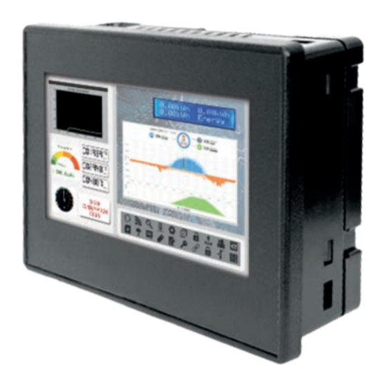
Page 11: Chapter 2: Introduction
CHAPTER 2: INTRODUCTION Visual Overview of i³C Lite Touch Screen (Press upper right corner to bring out the function keys and SYSTEM key to access the Main Menu.) Figure 2.1 – Visual Overview of the i³C Lite Page | 11... -
Page 12: Where To Find Information About The I³C Lite
2. Datasheets contain pin-outs, jumper settings, and other model specific information. b) User Manual – This manual provides general information that is common to i³C Lite models and can be downloaded from our website. Visit the IMO website to obtain user documentation and updates. IMO Precision Controls Ltd: http://www.imopc.com... -
Page 13: Connectivity To The I³C Lite
Connectivity to the i³C Lite. The i³C Lite has excellent capability for connecting to a variety of devices. The diagram below shows some examples of devices that can be used with the i³C Lite.. i³ i³ Other Devices Other Devices Smart I/O Drives Serial... -
Page 14: Features Of The I³C Lite
Features of the i³C Lite The i³C Lite are all-in-one industrial control devices. They combine control, user interface, I/O and networking into a single, integrated package. Unique features of the i³C Lite includes the following: • Small, sleek profile saves space and resources. •... -
Page 15: Accessories
Accessories Please visit the IMO Control Accessories website for communication, programming, and I/O accessories. IMO Precision Controls Ltd https://www.imopc.com/products/97660000 Page | 15... -
Page 16: Chapter 3: Mechanical Installation
NOTE: Unit comes with composite clips, which are tested for typical wash down, shock, and vibration. If metal mounting clips are needed, they can be ordered at the IMO Automation website. 1. Carefully locate an appropriate place to mount the i³C Lite. Be sure to leave enough room at the top of the unit for insertaion. -
Page 17: Mounting Clip Locations
Mounting Clip Locations Figure 3.1 – i³C Lite with Mounting Clip Location Mounting Orientation NOTE: For panel mounting—The orientation shown provides for optimum readability screen and ease of use of the keypad. Figure 3.2 – Orientation of i³C Lite Page | 17... -
Page 18: Panel Cutout
Panel Cutout For installations requiring NEMA 4X liquid and dust protection, the panel cutout should be cut with a tolerance of +/- 0.005” (0.1mm). Figure 3.4 – i³C Lite Dimensions Page | 18... -
Page 19: Factors Affecting Panel Layout Design And Clearances
Factors Affecting Panel Layout Design and Clearances WARNING: It is important to follow the requirements of the panel manufacturer and to follow all applicable electrical codes and standards. The designer of a panel layout needs to assess the requirements of a particular system and to consider the following design factors. -
Page 20: Temperature / Ventilation
Temperature / Ventilation Ensure that the panel layout design allows for adequate ventilation and maintains the specified ambient temperature range. Consider the impact on the design of the panel layout if operating at the extreme ends of the ambient temperature range. For example, if it is determined that a cooling device is required, allow adequate space and clearances for the device in the panel box or on the panel door. -
Page 21: Panel Layout Design And Clearance Checklist
3.12 Panel Layout Design and Clearance Checklist The following list provides highlights of panel layout design factors: ____Meets the electrical code and applicable standards for proper grounding, etc.? ____Meets the panel manufacturer’s requirements for grounding, etc.? ____Is the panel box properly connected to earth ground? Is the panel door properly grounded? Has the appropriate procedure been followed to properly ground the devices in the panel box and on the panel door? ____Are minimum clearance requirements met? Can the panel door be easily opened and closed? Is... -
Page 22: Chapter 4: Electrical Installation
The U.S. National Electrical Code (NEC) states the resistance to ground shall not exceed 25Ω. IMO Automation recommends less than 15Ω resistance from our equipment to ground. Resistance greater than 25Ω can cause undesirable or harmful interference to the device. -
Page 23: How To Test For Good Ground
How to Test for Good Ground In order to test ground resistance, a Ground Resistance Tester must be used. A typical Ground Resistance Meter Kit contains a meter, two or three wire leads, and two ground rods. Instructions are supplied for either a two-point or a three-point ground test. GROUND RESISTANCE METER GROUND DISCONNECTED... -
Page 24: Primary Power Port
Primary Power Port Table 4.1 – Primary Power Port Pins Signal Description 24VDC + / - 20% Input Power Supply Voltage Input Power Supply Ground Frame Ground 24VDC supply +/- 20% Figure 4.2– Power Connector (Primary Power Port) DC INPUT / FRAME Solid/Standard wire: 12-24 awg (2.05-0.511mm or 3.31-.205mm Strip length—0.28”... -
Page 25: Chapter 5: Serial Communications
CHAPTER 5: SERIAL COMMUNICATIONS Overview All i³C Lite models provide two serial ports, which are implemented with a single 8-position modular jack that is labeled MJ1/2. The MJ1 serial port is RS-232 while the MJ2 port is RS-485. MJ1 defaults to i³... -
Page 26: Rs-485 Termination And Biasing
RS-485 Termination and Biasing Termination—Proper RS-485 termination minimizes reflections and improves reliability. The MJ2 serial port allows an internal termination resistor to be placed across pins 1 and 2 by software control. Only the two devices physically located at the endpoints of the RS485 network should be terminated. -
Page 27: I³ Config Programming Via Serial Port
MJ1 is the serial port available for programming. The connection is RS-232 and is compatible with the IMO programming cable kits I3PC45. Unlike some other i³ models, the MJ2 port cannot be configured as a programming port. The Mini-B USB port is also available for programming. -
Page 28: Chapter 6: Can Communications
CHAPTER 6: CAN COMMUNICATIONS NOTE: For additional CAN information, refer to the CAN Networks manual on the website. Overview The i³C Lite provides a CAN networking port, which is implemented with an 8-position RJ-45 modular jack. The connector is labeled CAN and is red. CAN Connector on the i³C Lite. -
Page 29: Can Port Wiring
USB), and the PC CAN port is connected to the i³C Lite CAN port, then i³ Config can access the i³C Lite for programming and monitoring. In addition, the i³C Lite supports single-point-programming of all i³C Lite and other IMO controllers that are connected to a CAN network. If the PC COM port is connected to the i³C Lite programming port, then the i³C Lite can act as a pass-through gateway allowing i³... -
Page 30: Using Can For I/O Expansion (Network I/O)
Using CAN for I/O Expansion (Network I/O) Connecting remote I/O to the i³C Lite CAN port allows the i³C Lite I/O to be economically expanded and distributed. A variety of remote I/O modules is available for this purpose. CAN and Termination and Bias If there is a controller-to-controller communication on a network, and an i³C Lite will be at either end, then it is recommended that onboard electronic termination NOT be used. -
Page 31: Chapter 7: Ethernet Communications
Protocol / Feature Description ICMP Ping Internet Control Message Protocol EGD (Peer) Ethernet Global Data ICAN TCP Server IMO ICAN over Ethernet Modbus TCP Slave Modbus over Ethernet Ethernet / IP Server ODVA CIP over Ethernet FTP Server File Transfer Protocol... -
Page 32: Ethernet Module Configuration
Ethernet Module Configuration NOTE: The following configuration is required for all applications regardless of the protocols used. Additional configuration procedures must be performed for each protocol used. To configure the Ethernet Module, use i³ Config Programming Software to perform the following steps: On the main i³... - Page 33 Click the Config button to the right of LAN1, revealing the Ethernet Module Configuration dialog as shown in Figure 7.1 Figure 7.1 – Ethernet Module Configuration Configure the Ethernet Module parameters as follows: IP Address: Enter the static IP Address for the Ethernet Module being configured. NOTE: IP Addresses are entered as four numbers, each ranging from 0 to 255.
- Page 34 Status Register: Enter an i³ Register reference (such as %R100) to indicate which 16-bit i³ register will have the Ethernet Status word written to it. Table 7.3 shows how this register value is formatted and explains the meaning of each bit in the Status Word. Table 8.3 - Ethernet Status Word Register Format High Byte Low Byte...
-
Page 35: Ethernet Configuration - Ip Parameters
Ethernet Configuration – IP Parameters For primary operation, the IP address, Net Mask, and Gateway should be set in the LAN config of the I³ Config Hardware Configuration. There are options to get IP parameters from the LAN Config or to get parameters from registers. -
Page 36: Chapter 8: Downloadable Communication Protocols
CHAPTER 8: DOWNLOADABLE COMMUNICATION PROTOCOLS Overview Through loadable protocol device drivers, certain models of the i³ family can provide the ability to exchange data with remote devices such as variable-frequency drives, PLCs, and remote I/O devices. This feature greatly expands the i³ ’s control capability with negligible effect on the i³ ’s ladder scan time. - Page 37 In this case, the new i³ value is written to the target device. For triggered operations, only a Read or Write action is available. When downloaded to the i³ , the Scan List is scanned sequentially to generate data transactions with the remote device.
-
Page 38: Protocol Config
Protocol Config After opening I³ Config, choose Program → Protocol Config, and select the port drop-down box to select a protocol device driver. All protocol device drivers currently loaded in i³ Config are displayed in the dropdown selection. Some i³ models can be limited in the number of ports or number of protocol device drivers that can be selected. -
Page 39: Network Configuration
Network Configuration Network Configuration provides the required parameters to configure the network. Each protocol is different and may not require all the Network Config field. Please refer to the table below for the options in the Network Config field. Page | 39... - Page 40 Table 8.1 – Network Protocols Baud Rate, Data Bits, Stop Bits, These field define the bit level transfer over the serial port. Parity None – No handshake lines are used Handshake Multidrop Full – Rx remains active while Tx is occurring. Multidrop Half –...
-
Page 41: Device List And Device Configuration
Device List and Device Configuration Device List The Device List is reached from the Device button on the Protocol Config screen and provides a list of the configured devices on the Network. Devices must be created and exist in this list before corresponding Scan List entries can be created for this device. -
Page 42: Scan List
Scan List This can be accessed from the Scan List button on the Protocol Config screen or the Mapping button on the Device List screen and provides a Scan List of the Data Mapping entries. To transfer data between the I³ and remote target, a Scan List must be created that defines each transaction. Each mapping entry (transaction) contains the source and destination registers, the number of consecutive registers transferred, the direction of the transfer and what triggers the transfer. -
Page 43: Data Mapping Configuration (Scan List Entry)
Data Mapping Configuration (Scan List Entry) Update Type This field specifies the direction and what triggers the transfer of data between the i³ and target device for a mapping entry. Polled Read On every transaction scan, a read-only target device register(s) transaction occurs. Polled Read/Write On every transaction scan, a read target device register transaction occurs unless a local register value has changed. - Page 44 Polled Read/Write/Init On every transaction scan, a read target device register transaction occurs unless a local register value has changed. The write transaction only updates those local registers that have changed in value. If several non-consecutive local registers (contained in a single mapping entry) change value between transaction scans, it takes several consecutive scans to write each changed register.
-
Page 45: Chapter 9: System Setting And Adjustments
CHAPTER 9: SYSTEM SETTING AND ADJUSTMENTS System Menu - Overview The i³C Lite controller has a built-in System Menu, which lets the user view System Settings and make adjustments. To start the System Menu, press the upper right corner of the touchscreen to bring out the function keys, then press the SYSTEM key (or set %SR3 to 1), which will display the Main Menu. - Page 46 Sub-Menus Sub-Menus 192.168.0.1 NetM: 0.0.0.0 MJ1: GatWy: 0.0.0.0 (None Loaded) MAC ID: MJ2: 00:00:00:00:00:00 (None Loaded) CAN Ok? i³ C Lite CAN ID: COM: CAN Baud: 125kB (None Loaded) Menu Map Model: i3CL Mode: Idle Figure 9.2 Fkeys: Momentary Scan Rate(mS): Sys-Fn enable: Lcl Net Use(%): 0.0 All Net Use(%): 0.0...
-
Page 47: System Menu - Navigation And Editing
System Menu – Navigation and Editing As mentioned above, the System Menu is started by pressing the System key on the i³C Lite. Then, either press ESC to exit the System Menu, or use the keys to select an item and press Enter to display the item’s Sub-Menu. -
Page 48: System Settings Details
System Settings Details Set Network This sub menu allows setting for the CAN and Ethernet network to be viewed or changed. Displays the Ethernet IP address of the unit NetM: Displays the Ethernet net mask of the unit GatWy: Displays the Ethernet gateway of the unit MAC ID: Displays the Ethernet MAC ID of the unit CAN ID:... - Page 49 View Status The View Status Sub-Menu displays up to 18 System Settings. Only the Mode System Setting is editable. Model: Xxyyz = 5 or 6 character model number of this i³C Lite unit x is 1 for models that have a CAN port; 0 = no CAN port yy indicates the installed I/O module;...
- Page 50 View Diags The View Diags Sub-Menu displays up to 11 System Diagnostics, none of which are editable. The first two System Diagnostics are critical. If either of these indicate a Fault condition, then the i³C will not enter or remain in Run mode, and the problem must be investigated and corrected. Lite Ok = All executed ladder instructions are legal for loaded firmware Logic Error:...
- Page 51 The last nine System Diagnostics are informational. If any of them indicate a Warning condition, then can still enter and remain in Run mode, but the problem should be investigated and i³C Lite corrected. Ok = Application graphics objects loaded successfully User Graphics Fault = Application graphics objects not loaded, or load failed 0 = Watchdog timer has not tripped since the last power-up...
- Page 52 View Protocols The View Protocols Sub-Menu displays two System Settings, both of which are not editable. As mentioned in, both the MJ1 (Port 1) and MJ2 (Port 2) serial ports support downloadable protocols. To assign a downloadable protocol to an I³C LITE serial port, select the Protocol Config item in I³ Config’s Program menu and then setup a protocol for Port 1 or Port 2 (or both).
- Page 53 Set Fkeys The Set Fkeys Sub-Menu displays two System Settings, both of which are editable. Momentary = %K1-4 bits go On & Off as F1-F10 are pressed & released Fkeys: Toggle= %K1-10 bits toggle each time F1-F4 are pressed Yes = Reset and all clear system functions enabled SYS_Fn enable: No = Reset and all clear system functions disabled Page | 53...
- Page 54 Set Serial Ports The Set Serial Ports Sub-Menu displays three System Settings, all of which are editable, and one optional item. MJ1-232 = MJ1 – RS232 port is the default programming port Dflt Pgm Port No = MJ2 RS485 bias resistors are not switched in MJ2 RS485 Bias Yes = MJ2 RS485 bias resistors are switched in Set Time/Date...
- Page 55 Calibrate Analog When first entering this option, the user is presenting with information about the model and i³C Lite current state of the IO points. See Section 11.7 for more details. Model: i³CL12Y-*** I12-1: 000000000000 Q12-1: 000000000000 AI1: 12345 AI2: 456 AI3: 789 AI4: 32100 AQ1:...
- Page 56 Set Beeper The Set Beeper Sub-Menu displays one System Setting, which is editable. Yes (default) = Enables beeper Beeper enable: No = Disables beeper (does NOT affect ladder access) Page | 56...
- Page 57 Removable Media The Set Screen Sub-Menu displays four System Settings, all of which are editable. = Enable screen saver Saver enable: No (default) = Disable screen saver 5 - 1200 = Amount of time in minutes to expire with NO touch activity Timeout (min): before activating screen saver (black screen) Off (default) = Disable popup status...
- Page 58 Removable Media The Removable Media Sub-Menu displays the Removable Media Manager. After selecting Removable Media from the Main Menu, one of four Sub-Menu screens will appear: Media Directory = No microSD card has been installed in the Memory Slot No Card Media Directory = microSD card is installed, but it is still initializing Initializing...
- Page 59 Fail – Safe System The Fail-Safe System is a set of features that allows an application to continue running in the event of certain types of "soft" failures. These "soft" failures include: • Battery power loss • Battery-Backed Register RAM or Application Flash corruption due to, for example, an excessive EMI event.
- Page 60 Enable AutoRun “Enable AutoRun” displays the following options which can be selected: No = i³ will be in IDLE mode after AutoLoad or Automatic Restore. Enable AutoRun Yes =i³ will automatically be placed into RUN mode after AutoLoad or Automatic Restore. Enable AutoLoad “Enable AutoLoad”...
- Page 61 Clone Unit The ‘Clone Unit’ feature allows the user to “clone” the i³ of the exact same model. This feature “clones” application program and unit settings stored in Battery backed RAM of an I³ into the RM (refer Removable Media for details on using RM). It can then be used to clone a different I³ (exact same model).
- Page 62 Selecting “Create” will open the following screen: After confirmation, the i³ will create two new files in the root directory of the Removable Media Drive as shown below: AUTOLOAD.PGM Application file CLONE.DAT File having all unit settings and register values from Battery Backed RAM Page | 62...
- Page 63 Load Clone Selecting “Clone Unit” menu will open the following menu screen. Select “Load”. NOTE: For security enabled files, Load Clone asks for password validation before loading the application. Page | 63...
-
Page 64: Touch Screen Calibration
Touch Screen Calibration The touch screen is calibrated at the factory and rarely needs modification. However, if actual touch locations do not appear to correspond with responding objects on the display, field adjustment is available. To access the field adjustable touch screen calibration dialog, press the far upper right corner of the touchscreen to bring out the function keys, then press and hold the SYSTEM key for longer than five (5) seconds and a menu with several advanced functions will appear. - Page 65 Figure 9.3—Screen Calibration Page | 65...
-
Page 66: Chapter 10: Removable Media
CHAPTER 10: REMOVABLE MEDIA 10.1 Overview models provide a Removable Media slot, labeled Memory, which supports standard microSD i³C Lite flash memory cards. microSD cards can be used to save and load applications, to capture graphics screens, and to log data for later retrieval. Figure 10.1 –... -
Page 67: Microsd File System
10.3 microSD File System supports displaying files in the 8.3 format, i.e. filename.pgm. Files with up to 8 characters i³C Lite as a file name before the dot and up to 3 characters as a file extension after the dot will display in full on the screen. -
Page 68: Using Removable Media To Log Data
10.5 Using Removable Media to Log Data Using Read and Write Removable Media function blocks, an application ladder program can read and write register data in the form of comma-delimited files, with a .CSV extension. These files are i³C Lite compatible with standard database and spreadsheet PC programs. -
Page 69: Using Removable Media To View And Capture Screens
10.7 Using Removable Media to View and Capture Screens The i³C Lite File System uses bitmap files with the .BMP extension or JPEG files with the .JPG extension to store i³C Lite graphic screen captures. To view a captured i³ screen, use the Removable Media Manager to find and highlight the desired .BMP or .JPG file, and then press Enter. -
Page 70: Removable Media (Rm) Features-Program Logic
10.9 Removable Media (RM) Features—Program Logic NOTE: For detailed information regarding RM function blocks and parameters, refer to the help file in I³ Config Software. Refer to “USB Flash Media support for RM Functions” for USB flash drive access details. The following RM function blocks are available in i³... -
Page 71: 10.10 Removable Media (Rm) Features- Program Features
10.10 Removable Media (RM) Features— Program Features a. Datalog Configuration—This feature allows the controller to periodically log register values to Removable Media. The register data is stored in .csv (comma separated value) format, which is compatible with 3 party PC applications, such as Microsoft Excel. b. -
Page 72: 10.13 Filenames Used With The Removable Media (Rm) Function Blocks
10.13 Filenames used with the Removable Media (RM) Function Blocks The i³C Lite supports displaying files in the 8.3 format, i.e. filename.pgm. Files with up to 8 characters as a file name before the dot and up to 3 characters as a file extension after the dot will display in full on the i³C Lite screen. -
Page 73: 10.14 System Registers Used With Rm
10.14 System Registers used with RM %SR174 - Removable Media Protect. Write a one (1) to %SR174 to prohibit read/write access to the removable media card. Write a zero (0) to allow access. %SR175 Status – This shows the current status of the RM interface. %SR176 Free Space –... -
Page 74: 10.15 Safe Removal Of Removable Media Card
10.15 Safe Removal of Removable Media Card If the Removable Media card should need to be removed during operation, it can be safely removed by moving a one (1) into %SR174. This prevents corruption to the file system if the card is removed during a file-write sequence. -
Page 75: Chapter 11: General I/O
CHAPTER 11: GENERAL I/O NOTE: Each i³C Lite unit is shipped with a datasheet in the box. The datasheet is the first document to refer to for model-specific information related to i³C Lite models. The web version of this manual has all of the i³C Lite datasheets attached to it. -
Page 76: Solid-State Digital Outputs
Table 11.1– I/O and Model Overview Solid State I³C Lite Relay Analog Digital Digital Inputs Analog Inputs Models Outputs Outputs Outputs ✓ ✓ ✓ ✓ i³C Lite 10D12 ✓ ✓ ✓ ✓ ✓ i³C Lite 10D14 Table 11.1 shows the different types of I/O included with the two i³C Lite models. Specifications and wiring diagrams can be found on the data sheets. - Page 77 The digital outputs in the i³C Lite are typically controlled via %Q bits in the register mapping. Some of the outputs are designed for high-speed applications and can be used for PWM or frequency output applications. Please see the data sheet and Chapter 12 on High-Speed I/O for additional information.
- Page 78 Figure 11.2 –Relay and Digital Output Page | 78...
-
Page 79: Relay Outputs
Some protective measures must be determined by an engineer. Below are some recommendations that will work for many applications. If there are additional questions on protection from inductive load, consult IMO Technical Support. DC Loads – General purpose diode (IN4004) in reverse bias across the load. -
Page 80: Sinking And Sourcing Outputs
11.5 Sinking and Sourcing Outputs Figure 11.3 – Model-10D14: Sinking and Sourcing Outputs Page | 80... -
Page 81: Digital Inputs
11.6 Digital Inputs NOTE: See Chapter 12 for High Speed I/O information and refer to the datasheet for i³C Lite model being used for details on jumper settings. NOTE: The digital inputs on the i³C Lite are designed for low voltage DC inputs. The inputs are designed to support both positive and negative input modes. - Page 82 Figure 11.5 –Digital Input Page | 82...
-
Page 83: Analog Inputs
11.7 Analog Inputs NOTE: See the datasheet and Chapter 15 for details on how to use i³ Config to configure the digital filtering. The analog inputs on the i³C Lite allow current measurement from a variety of devices. The analog inputs have a digital filter that can be used to filter electrical noise that may be unavoidable in some installations. - Page 84 11.8.2 I-O Calibration This controller has a field calibration option in the System Menu. The calibration option can be used to achieve better accuracy than factory specifications and to compensate for calibration offsets that could occur with additional connectors and environmental conditions. Calibration is stored in non- volatile memory and is retained even if the backup battery fails or is removed.
- Page 85 To calibrate 0-20mA, 4-20mA, or RTD PT100 Analog Inputs: NOTE: During Calibration process, the application may be placed in Idle. 1) Select the channel and mode as described above 2) Connect the analog channel to be calibrated to the calibration equipment. 3) Apply the lower current or RTD value as directed by the screen to the selected analog input channel.
-
Page 86: Rtd Wiring On J3 Connector
11.9 RTD Wiring on J3 Connector Page | 86... -
Page 87: 11.10 4I³C Lite-20Ma Wiring For Input And Output
Figure 11.7 – RTD Wiring on J3 11.10 4i³C Lite-20mA Wiring for Input and Output Figure 11.8 – 4-20mA Wiring on J3 Page | 87... -
Page 88: 11.11 Analog Inputs
11.11 Analog Inputs NOTE: See the data sheet and Chapter 15 for details on how to use i³ Config to configure the digital filtering. The analog inputs on the i³C Lite allow current measurement from a variety of devices. The analog inputs have a digital filter that can be used to filter electrical noise that may be unavoidable in some installations. -
Page 89: Chapter 12: High Speed I/O (Hsc/Pwm)
CHAPTER 12: HIGH SPEED I/O (HSC/PWM) 12.1 Overview In addition to the compliment of simple analog and digital I/O, the i³C Lite supports High Speed Counting (HSC) I/O functions and may support Pulse Width Modulation (PWM) Output functions. The HSC functions include frequency, totalizing, pulse width, and quadrature measurement. The PWM functions include traditional PWM (with variable rate and duty) with variable acceleration and deceleration rates. -
Page 90: High Speed Counter (Hsc) Functions
12.3 High Speed Counter (HSC) Functions Four dedicated inputs are available that can be configured for one of four modes of operation. Those modes are Frequency, Count (totalize), Pulse width or period (pulse) and Quadrature measurement. For some modes, more than one HSC input may be consumed. The measurement value is provided to ladder in a %AI register. - Page 91 12.3.2 Totalize In totalize mode, the accumulator is simply incremented each time the input transitions in a specific direction. Totalize mode is configurable to specify the edge (rising or falling) on which the accumulator is incremented. Rising Edge Signal Falling Edge Signal Three different options are available to reset the current count.
- Page 92 12.3.3 Pulse In pulse mode, the high-speed input can measure the width or period of a pulse stream in one of four modes and provides a continuous indication of the last sampled value. Width High 1μs Counts – In this sub-mode the accumulator value will contain the number of 1μs counts for which the pulse is high.
- Page 93 12.3.4 Quadrature Two HSC inputs are consumed for each of the two possible Quadrature counters. For example, selecting quadrature mode for HSC 1 will use HSC inputs 1 and 2, which correspond to A and B quadrature signals. Therefore, HSC 1 and 3 may be configured for quadrature input. Alternately, HSC 3 may be configured to reset HSC1 (quadrature) count on a marker input Quadrature mode works much like the totalizer except the accumulator will automatically increment or decrement based on the rotation phase of the two inputs.
- Page 94 Three different options are available to reset (or set) the current count. They are: • Configured Counts per Rev value When configuring the quadrature function, a value may be specified under the Counts per Rev column. When rotation produces an increasing count, the quadrature accumulator resets to zero on reaching the Counts per Rev count.
- Page 95 Asynchronous modes ignore the quadrature inputs and reset the quadrature accumulator to zero on the configured edge (rising, falling or both). These are the most common settings used. When configuring, asynchronous mode selections are prefixed with the word Async. Synchronous modes synchronize the reset (or set) to the selected quadrature input and the selected marker polarity.
- Page 96 The accumulator is reset to zero on the specified edge if rotation is clockwise (as shown in Figure 10.1 above). However, if rotation is reversed, the accumulator is alternately set to Counts per rev – 1 on that same physical edge. When direction is reversed, that same physical edge is seen (by the internal decoder) as having the opposite edge polarity as shown below.
-
Page 97: Hsc (High Speed Counter)
12.4 HSC (High Speed Counter) When either Q1 or Q2 is configured for HSC operation, HSC1 or HSC2 totalize functions are extended to allow respective direct output control based on a comparison of the current count and a preset value (PV). See totalize in the HSC section above for more information. 12.4.1 HSC Functions Register Map Table 12.3 –... - Page 98 12.5.2 PWM When either Q1 or Q2 is configured for PWM, the PWM function drives that respective output. Both PWM channels may be individually enabled and can have independent frequency and duty cycles. Duty Cycle – The Duty Cycle is a 32-bit value from 0 to 32,000 indicating the relative duty cycle of the output.
- Page 99 12.5.3 PWM Output Waveform Figure 12.4 – PWM Output Waveform Table 12.4 – PWM Output Waveform Table Rise Time 150ns Max Fall Time 150ns Max PWM Period Frequency = ������������ Page | 99...
-
Page 100: Pwm Functions Register Map
12.6 PWM Functions Register Map Register %AQ3 HSC1 Preset Value (AQ3-4) %AQ4 %AQ5 HSC2 Preset Value (AQ5-6) %AQ6 %AQ7 PWM1 Duty Cycle (32-bit) %AQ8 %AQ9 PWM1 Frequency (32-bit) %AQ10 %AQ11 PWM2 Duty Cycle (32-bit) %AQ12 %AQ13 PWM2 Frequency (32-bit) %AQ14 Table 12.5 –... -
Page 101: Chapter 13: User Interface
CHAPTER 13: USER INTERFACE 13.1 Overview This chapter presents the user interface (or operator view) of the i³C Lite and some of the model specific characteristics of the i³C Lite as compared to the rest of the i³ line. This chapter does NOT cover building screens or using the i³... -
Page 102: Numeric Keypad
On objects that represent non-discrete information, more action may be required beyond that of simply touching the object. For example, the slider object requires the operator to touch and slide the control in the direction desired. Alternately, alpha-numeric entry objects invoke a pop-up alpha- numeric keypad for additional user input. - Page 103 Once the desired value is entered, pressing the Enter key moves that value into the object (and the corresponding i³ register) and the alpha-numeric keypad disappears. Alternately, pressing the ESC key any time before the Enter key cancels the operation, leaves the objects current value unchanged, and the alpha-numeric keypad disappears.
- Page 104 ASCII Object When editing an ASCII value, an ASCII keypad is displayed as shown Figure 12.3. The ASCII keypad has three (3) modes, numeric, symbols, and alpha. In Alpha mode, the Caps Lock button may be pressed to access capital letters. When you first enter this editor, typing a character will overwrite the entire old string and start a new entry.
-
Page 105: Screen Navigation
13.4 Screen Navigation To allow the operator to change screens, a screen jump object is generally used. This object may be visually represented as a 3-D button (responding to touch) or remain invisible and logically tied to an I³ register. An optional system ICON may be configured for display along with the legend, which aids in identifying the object as one that causes a screen change (shown below in figure 14.4). -
Page 106: Ladder Based Screen Navigation
13.5 Ladder Based Screen Navigation Ladder logic can use several techniques to control screen navigation. Coils can be tied to %D registers to make them screen coils. These coils have two modes: switch and alarm. If the ladder program energizes an alarm display coil, the screen associated with this coil is displayed and overrides the normal user screens. -
Page 107: Touch (Slip) Sensitivity
13.6 Touch (Slip) Sensitivity Touch slip sensitivity is preset to meet most applications; however, adjustment is available to reduce the sensitivity for touch release. That is, once a graphical object (button) is touched and held by a finger, the default touch slip sensitivity allows for a slight slip of the finger on the graphical object before the i³C Lite assumes touch been released (equates to approximately a quarter inch of movement with a stylus). -
Page 108: Alarms
13.7 Alarms Alarm presentation to the operator is highly configurable and beyond the scope of this document to describe fully. The alarm object is generally used to enunciate alarms to the operator. Alarm presentation to the operator is highly configurable and beyond the scope of this document to describe fully. - Page 109 The currently selected entry is indicated by a yellow highlight which can be moved up or down by touching the arrow buttons or by directly touching an entry. If more entries exist than can fit on the page, a scroll bar is displayed on the right side that also indicates the current relative position. The current state of the displayed alarm is indicated by its color and optionally by an abbreviated indicator after the date/time stamp (ALM, ACK, RTN).
- Page 110 Figure 13.8—Alarm Configuration in i³ Config Page | 110...
-
Page 111: Removable Media
13.8 Removable Media The removable media object is generally used to inform the operator on the current state of the removable media device and allow access to its file structure. The removable media object is displayed as a button that changes colors to indicate the current state of the removable media device. The following indicates the device states and the default colors associated with these states. - Page 112 The currealibartioncntly selected entry is indicated by a yellow highlight which can be moved up or down by touching the arrow buttons or by directly touching an entry. If more entries exist than can fit on the page, a scroll bar is displayed on the right side that also indicates the current relative position. File operations are accomplished by pressing the appropriate button at the bottom of the removable media viewer.
-
Page 113: Screen Saver
13.9 Screen Saver The i³C Lite screen backlight life remains sufficiently bright for five (5) years. It will dim to 70% brightness if it is left on continuously for five (5) years. If the application does not require interaction with the i³C Lite for long periods of time, the backlight life can be extended by using the screen saver function. -
Page 114: Registers
CHAPTER 14: REGISTERS 14.1 Register Definitions When programming the i³C Lite, data is stored in memory that is segmented into different types. This memory in the controller is referred to as registers. Different groups of registers are defined as either bits or words (16 bits). - Page 115 Table 14.3 – %SR Registers Register Name Description Min Val Max Val %SR1 USER_SCR Current User Screen Number 1023 %SR2 ALRM_SCR Current Alarm Screen Number (0=none) 1023 %SR3 SYS_SCR Current System Screen Number (0=none) %SR4 SELF_TEST Bit-Mapped Self-Test Result 65535 %SR5 CS_MODE Control Station Mode (0=Idle, 1=Do I/O, 2=Run)
- Page 116 Table 14.3 – %SR Registers Register Name Description Min Val Max Val %SR48 RTC_MON Real-Time-Clock Month %SR49 RTC_YEAR Real-Time-Clock Year 1996 2095 %SR50 RTC_DAY Real-Time-Clock Day (1=Sunday) %SR51 NET_CNT Network Error Count 65535 %SR52 WDOG_CNT Watchdog-Tripped Error Count 65535 %SR53-55 Reserved %SR56 LAST_KEY...
- Page 117 Table 14.3 – %SR Registers Register Name Description Min Val Max Val %SR186 SCR_SA_TM Screen Saver Time in minutes (delay) 1200 %SR187 NET_USE Average Net Usage of all units on the CAN network 1000 Minimum Net Usage of all units on the CAN %SR188 NET_MIN 1000...
-
Page 118: Register Map For I³C Lite I/O
14.3 Register Map for i³C Lite Table 14.4 – Register Map for i³C Lite I/O Fixed Digital/Analog i³C Lite Models Address I/O Function Digital Inputs 1-12 1-12 Reserved 13-32 13-32 Digital Outputs 1-12 Relay Outputs Reserved 9-16 13-16 Analog Inputs Reserved 5-12 5-12... -
Page 119: Resource Limits
14.4 Resource Limits Resource Value Resource Value 1024 ICAN 125kBd, 250kBd, 500kBd, or 1MBd 1 RS232, 1 RS485 Ports 1024 Serial Ports (Single Connector) IDs Per ICAN 64 w/o repeat (253 w/ 3 repeaters) Network Keypad Slide Keys (Touch) 1024 Display 4.3”... -
Page 120: Chapter 15: I³ Config Configuration
CHAPTER 15: I³ CONFIG CONFIGURATION 15.1 Overview i³C Lite hardware is programmed with a Windows based PC application called i³ Config. This application can be used to program, configure, monitor, and debug all aspects of the i³C Lite unit. Please see the on-line help provided with i³... -
Page 121: Establishing Communications
15.3 Establishing Communications The i³C Lite can communicate with i³ Config using USB to USB, USB to serial adapters, serial port communications via MJ1 Port, Ethernet (with an Ethernet adapter board), onboard Ethernet Port, CAN (iCAN), or modems. For i³C Lite, use i³ Config Version 9.80 or newer. To communicate with the i³C Lite via USB you will need the Automated Driver Installer located on the Microsoft website . - Page 122 The PC will detect a new device has been plugged into the USB port. Open i³ Config and the first screen to open will be the Connection Wizard. Select USB and Next>> then Finish. Page | 122...
- Page 123 If the Connection Wizard does not pop up upon opening I³ Config, then select Controller (in the I³ Config tool bar) → Connection Wizard, choose your connection method. If you are connecting for the first time, we suggest connecting via USB. Figure 15.3 –...
- Page 124 An alternate way to select the COM setting is to go to i³ Config → Tools → Application Settings → Communication → Configure and choose connection method in Add Target. Figure 15.4 – i³ Config: Alternative Connection Method Screenshot Page | 124...
- Page 125 Figure 15.5 – Add Target Screenshot in I³ Config NOTE: The following fields need to be filled for communication configuration if i³ Config Connection Wizard was not used. Table 15.1 explains the information needed in each field. 1. Target Name 2.
- Page 126 NOTE: i³ Config will do necessary initialization for the selected internal modem. Select this option to communicate over USB. Now IMO devices and IMO USB to serial converters are recognized and can be specifically selected. Connected Device NOTE: This configuration is required if the controller to which i³...
- Page 127 If communication is established, the target indicator will show the mode of the controller Target: yy(R) as shown in the status section above in this chapter, section I³ Config Status Bar. When connected directly to the controller to which i³ configurator communications are required, the Local ID and the Target ID should match.
-
Page 128: Communicating Via Mj1 Serial Port
15.4 Communicating via MJ1 Serial Port Start by configuring i³ Config to use the correct communications port. This can be done using the Tools → Application Settings → Communication dialog in I³ Config. Next connect the PC serial port to the port labeled MJ1 on the i³C Lite. NOTE: If communications are successful, the target indicator should show the mode of the controller Target: yy(R) as shown in the status section above. -
Page 129: Communicating Via On Board Ethernet Port
15.5 Communicating via On Board Ethernet Port The i³C Lite Ethernet address may be set from the System menu depending on the program currently loaded into the i³C Lite. To check or change the Ethernet address on the i³C Lite, press in the far upper right corner of the touch screen to bring out the function keys, then press the System Menu key. - Page 130 16. Click OK all the way back to the main i³ Config window. It may take a moment to initialize the communications. 17. Check the status bar for successful communications. Examples of the PC Ethernet setup and the i³ Config Ethernet setup mentioned in the above steps. Figure 15.7 –...
- Page 131 Figure 15.8 – I³ Config Ethernet Settings To configure the Ethernet settings of the i³C Lite using i³ Config, go to Controller → Hardware Configuration. If not already done, select the correct connected controller, or use the Auto Config button to automatically recognize a controller that is already successfully connected to I³ Config. Below the main controller configuration, under Network Ports, find LAN1, and click on the Config button to the right of the greyed-out ETN300.
- Page 132 Figure 15.9 – LAN1 Configuration Dialog If Get settings from is set to Configuration for any parameter, the addresses in the Default Settings column will take place when this program is loaded and every time this controller enters RUN mode. Registers may optionally be defined that will reflect the settings.
-
Page 133: Configuration
(2) If the i³C Lite is connected to the PC press the Auto Config System button to automatically detect the Base model, I/O and any communication options. (3) If the i³C Lite is NOT connected: a. Select Series → i3C Lite Series b. Select Device Type → i3C LITE c. Select Model # → i3CL12Y/10D14-SEHF or i3CL12Y/10D12-SEHF (4) Select Local I/O →... -
Page 134: Digital / Hsc Input Configuration
Configuring the i³C Lite I/O has four main portions that are covered in this chapter. For additional information on I/O, refer the chapters covering General I/O (Chapter 11) or High Speed I/O (Chapter 12) in this manual. The four areas of I/O configuration are: Digital In / HSC Digital Out / PWM Analog In... - Page 135 The Digital Input Active Mode group box allows the user to select if inputs are active high (Positive logic) or active low (Negative logic). The High-Speed Counters group box contains all of the windows that are used to configure the four available high-speed counters on the i³C Lite.
-
Page 136: Digital / Pwm Output Configuration
15.8 Digital / PWM Output Configuration The following figure illustrates the Digital / PWM Output Configuration dialog. Figure 15.11 – Digital / PWM Output Configuration Dialog The Q1 and Q2 group boxes allow the user to specify the operation of the multi-function outputs. The PWM State on Controller Stop group box contains items that allow the user to specify how the PWM outputs behave when the controller is stopped. -
Page 137: Analog Input Configuration
15.9 Analog Input Configuration The following figure illustrates the Analog Input Configuration dialog. Figure 15.12– Analog Input Configuration Dialog The Channel x drop down windows allows the user to specify the mode for each analog input to operate. The Channel x drop down windows are enabled/disabled according to which model is being configured. -
Page 138: 15.10 Analog Output Configuration
15.10 Analog Output Configuration The following figure illustrates the Analog Output Configuration dialog. [Controller → (Select Series & Device Type) → Local I/O → Config → Module Setup → Analog Output Configuration} Figure 15.13 – Analog Output Configuration Dialog The Output value on Stop group box contains items that allow the user to specify how the analog output channels behave when the controller is stopped. -
Page 139: 15.11 Scaling Analog Inputs
15.11 Scaling Analog Inputs To access the Advanced Math Scaling function, select Tools → Project Toolbox. This will open a side bar, and then select Advanced Math → Scale. Page | 139... - Page 140 Example 1 The i³ Config Scale function, found in the Advanced Math functions, allows for very easy conversion of the raw input value into a meaningful reading. For example, a pressure transducer may be specified as a 4-20mA signal to signify a 0-2000 psi pressure reading. With the analog channel set to the 4..20mA range, the raw analog input value, which is in INT format ranges from 0 to 4mA to 32000 for 20mA.
-
Page 141: Chapter 16: Fail - Safe System
CHAPTER 16: FAIL – SAFE SYSTEM 16.1 Overview The Fail-Safe System has the following capabilities: • Manually backup the current Battery-Backed RAM Register Settings into flash memory. • Manually restore Register Settings from the values previously backed up in flash to Battery- Backed RAM. -
Page 142: Settings
16.2 Settings To use the fail – safe feature, the user must do the following: 1. Backup the current Battery-Backed RAM Register contents in On-Board flash memory using System Menu options. 2. From I³ Config, create AUTOLOAD.PGM for the application program using ‘Export to Removable Media’. - Page 143 Backup i³ Data: When initiated, this will allow the user to manually copy Battery-Backed RAM contents on to the onboard flash memory of the i³. This will have the effect of backing up all the registers and controller settings (Network ID, etc.) that would otherwise be lost due to a battery failure. %SR164.4 is set to 1 when backup operation is performed.
- Page 144 Restore i³ Data: When initiated, this will allow the user to manually copy the backed-up data from the onboard flash memory to the Battery-Backed RAM. A restore operation will be automatically initiated if a backup has been previously created and on power-up the Battery-Backed RAM registers fail their check.
- Page 145 Clear Backup Data: When initiated, the backup data will be erased from the onboard flash and no backup will exist. %SR164.4 and %SR164.3 is reset to 0 when backed up data is erased. Figure 16.5 – Clear Backup Data Exit: Goes back to the previous screen. Page | 145...
- Page 146 The i ³ follows the following sequence in execution of Automatic Restore: Figure 16.6 – Flow Chart for Automatic Restore Page | 146...
-
Page 147: Autoload
16.4 AutoLoad This system menu option allows the user to specify whether the i³ automatically loads the application AUTOLOAD.PGM located in Removable Media. When the AutoLoad setting is enabled (set to YES), it can be manually or automatically initiated at power-up. - Page 148 The i³ implements the following sequence to execute the AutoLoad function: Figure 16.8 – Flow Chart for AutoLoad Page | 148...
-
Page 149: Autorun
16.5 AutoRun This system menu option, when enabled (YES), allows the user to automatically place the i³ into RUN mode after the AutoLoad operation or automatic Restore Data operation. When the AutoRun setting is disabled (NO), the i³ remains in the IDLE mode after a Restore Data or AutoLoad operation. -
Page 150: Chapter 17: Clone Unit
CHAPTER 17: CLONE UNIT 17.1 Overview The ‘Clone Unit’ feature allows the user to “clone” the i³ of the exact same model. This feature “clones” application program and unit settings stored in Battery backed RAM of an i³ into the RM. It can then be used to clone a different i³... - Page 151 2. Selecting “Clone Unit” menu will open the following screen: Figure 17.2 – Clone Unit Menu before Cloning NOTE: In the above Figure 17.2, F3 and F4 are inactive in the clone Unit. 3. Make/Create Clone option enables the user to duplicate / Clone an application file, all unit settings and all register values from Battery Backed RAM.
- Page 152 After confirmation, the i³ will create two new files in the root directory of the Removable Media Drive as shown below: AUTOLOAD.PGM Application file CLONE.DAT File having all unit settings and register values from Battery Backed Figure 17.4 – Clone Unit Files NOTE: Make/Create clone operation automatically includes the security in AUTOLOAD.PGM file for security enabled files.
- Page 153 4. Once the cloning is successful, the i³ gives a message as below: Figure 17.5 – Cloning Status Make/Create clone can also be triggered by setting %SR164.9 bit to “1” from Ladder program or graphics. Once the operation is completed, this bit is made zero (0) by the firmware. When Make clone operation is triggered by this SR bit, it does not ask the user for confirmation to make the clone.
-
Page 154: Load Clone
17.3 Load Clone This option loads the application, all unit settings and register values from Removable Media to the battery-backed RAM (regardless of AutoLoad settings), and then resets the i³ for the settings to take effect. User must perform the following to Load the Clone: 1. - Page 155 3. User must confirm Load Clone as shown below: Figure 17.8 – Load Clone Confirm Screen 4. After confirmation, all unit settings and register values will be loaded from the Removable media to the Battery backed RAM (Regardless of AutoLoad settings) and then the i³ resets at which stage the settings take effect.
-
Page 156: Chapter 18: Maintenance
CHAPTER 18: MAINTENANCE 18.1 Firmware Updates The i³C Lite. products contain field updatable firmware to allow new features to be added to the product at a later time. Firmware updates should only be performed when a new feature or correction is required. -
Page 157: Backup Battery
WARNING: EXPLOSION HAZARD—BATTERIES MUST ONLY BE CHANGED IN AN AREA KNOWN TO BE NON-HAZARDOUS. The i³C Lite uses a 3V Lithium Coin battery which can be ordered from IMO. Below are the steps to replace the battery. 1. Make sure the user program and any data stored in retentive memory is backed up. -
Page 158: Chapter 19: Modbus Communications
CHAPTER 19: MODBUS COMMUNICATIONS 19.1 Modbus Overview For complete Modbus instructions, please refer to the Help file in I³ Config. Modbus (serial) is a popular, de-facto standard protocol that allows industrial devices from multiple manufacturers to easily share data in real-time. For Modbus serial communications, the i³C Lite. can act as either a Master or a Slave. -
Page 159: Modbus Master Overview
Modbus addressing style for each slave on the network, minimal address conversion is required. Also, if the slave is another IMO product (i.e. another I³), the “Native Addressing” option can be selected (i.e. %R1, %M17, etc.), and this skips the conversion to Modbus style altogether. -
Page 160: 19.4 Opening I³ Config Help File
19.4 Opening I³ Config Help File After opening the i³ Config Help file, select the Index table and search for “Modbus Slave” or “Modbus Master”, as shown below. Select “Index” tab. Page | 160... -
Page 161: Modbus Addressing Table For I³C Lite Units
19.5 Modbus Addressing Table for i³C Lite Units To access i³C Lite registers, a Modbus Master must be configured with the appropriate register type and offset. This is usually accomplished with one of two methods: Method 1: The first method uses Traditional Modbus References, in which the high digit represents the register type and the lower digits represent the register offset (starting with Register 1 for each type). -
Page 162: Chapter 20: Troubleshooting / Technical Support
CHAPTER 20: TROUBLESHOOTING / TECHNICAL SUPPORT Chapter 20 provides commonly requested troubleshooting information and checklists for the following topics. 20.1 Connecting to the i³C Lite I³ Config connects to the local controller automatically when the serial connection is made. The status bar below shows an example of a successful connection. -
Page 163: Connecting Troubleshooting Checklist (Serial Port - Mj1 Programming)
4. Check that a Loaded Protocol or ladder is not actively using MJ1. Taking the controller out of Run Mode from the System Menu on the controller will make MJ1 available to i³ Config. 5. Successful communications with USB-to-serial adapters vary. If in doubt, IMO offers a USB to serial adapter. Part numbers PC501 20.3... -
Page 164: Local Controller And Local I/O
20.5 Local Controller and Local I/O The system menu provides the following status indications that are useful for troubleshooting and system maintenance. • Self-test results, diagnostics. • RUN and OK status • Network status and usage • Average logic scan rate •... -
Page 165: Ican Network Troubleshooting Checklist
20.8 ICAN Network Troubleshooting Checklist 1. Use the proper Belden wire type or equivalent for the network as specified. 2. The i³C Lite does not provide 24VDC to the network. An external voltage source must be used for other devices . 3. -
Page 166: Basic Troubleshooting
Lite will not download project file. file and not a .csp file. 20.10 Technical Support Contacts For manual updates and assistance, contact Technical Support at the following locations: IMO Precision Controls Ltd: Tel: +44 (0) 1707 414 444 Web: https://www.imopc.com Email: automation@imopc.com... - Page 167 Page | 167...
Need help?
Do you have a question about the i3C Lite and is the answer not in the manual?
Questions and answers